4
© Copyright 2008 Zoeller Co. All rights reserved.
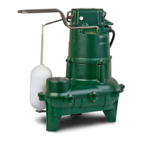
(1) Double seal pumps offer extra protection from damage caused by seal failure.
(2) Pumps should be serviced on a periodic preventative maintenance schedule.
(3) Oil in the motor housing and lower seal cavity must be changed when pump is serviced. If oil from the motor housing contains water or other contamination,
both seals should be replaced during maintenance. Always replace with new factory recommended oil and service parts. All repairs must be made by Zoeller
Authorized Service Stations.
DOUBLE SEAL PUMPS (4000 SERIES ONLY)
THREE PHASE WIRING INSTRUCTIONS
FOR YOUR PROTECTION, ALWAYS
DIS CON NECT PUMP FROM ITS POWER SOURCE
BE FORE HAN DLING.
To automatically operate a nonautomatic three phase pump, a
control panel is required. Follow the in struc tions pro vid ed with the
panel to wire the system. For automatic three phase pumps see
automatic 3 phase wiring di a gram located to the far right.
Before installing a pump, check the pump rotation to en sure that
wiring has been connected prop er ly to power source, and that
the green lead of pow er cord (See wiring di a gram), is con nect ed
to a valid ground. Mo men tari ly en er gize the pump, observing the
di rec tions of kick back due to start ing torque. Ro ta tion is correct if
kick back is in the op po site direction of rotation arrow on the pump
cas ing. If rotation is not correct, switching of any two power leads
other than ground, should provide the proper rotation.
All three phase pumps require motor starting devices with motor
overload pro tec tion. See FM0514 for simplex in stal la tions or
FM0486 for duplex in stal la tions. Pumps must be in stalled in
ac cor dance with the National Electrical Code and all ap pli cable
local codes and or di nanc es. Pumps are not to be installed in
locations clas si fi ed as haz ard ous in accordance with National
Elec tri cal Code, ANSI/NFPA 70.
NONAUTOMATIC
3 PHASE
AUTOMATIC
3 PHASE
(3)
FLOAT
(1)
(2)
BLUE
TAN
COM
NC
CR
RELAY
7
8
B
ORANGE
A
1
2
3
4
(M1)
(M2)
96
4
5
WINDINGS
RED
YELLOW
PURPLE PURPLE
OR BROWN
BLACK
RED
WHITE
GREEN
L3L2L1
THERMOSTAT
WHITEWHITE
WHITE
RED
BLUE
MOTOR
(3)
BLUE
RED
BLACK
GREEN
L1
L2
006848
(1)
(2)
YELLOW
L3
WHITE
RED
013071
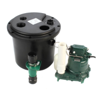
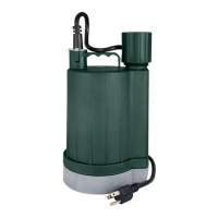
WD & WH MODEL INSTALLATION
WIRING DIAGRAM FOR MODELS
WD - 230V, 1 Ph, 60 Hz.
WH - 200/208V, 1 Ph, 60 Hz.
Models WD & WH are fully automatic. A fl oat switch is in clud ed and
fac to ry wired in the pump circuit to provide automatic operation
once the fl oat switch is secured prop er ly to the outlet pipe. Use the
di a gram above to secure the fl oat switch properly and obtain the
proper tether to cus tom ize the on-off cycle to each ap pli ca tion.
Determining Pumping Range
in Inches (1 inch - 2.5 cm)
Tether Length 5 10 15 20 22
Pumping Range 9 13.5 18 22 24
max.
Use only as a guide. Due to weight of
ca ble, pump ing range above hor i zon tal
is not equal to pumping range be low
hor i zon tal. Ranges are based on test ing in
nonturbulent con di tions. Range may vary
due to water tem per a ture and cord shape.
As teth er length in creas es, so does the
vari ance of the pump ing range.
min.
START
RUN
BLUE
MOTOR
(WHITE)
RED
(BROWN)
O.L.
YELLOW
(BLACK)
SWITCH
FLOAT
BLACK
BLACK
WHITE
CAPACITOR
BLUE
(1)
(2)
RED
RUN
WHITE
GREEN
L1
L2
(3)
011835
Note: Failure to keep within proper teth er limits
may prevent reliable switch op er a tion.
Note: Cable must be mounted in hor i zon tal
position.
22" MAX.
5" MIN.
20 AMP SWITCH (WD & WH MODELS)
SK305
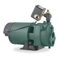
SINGLE PHASE WIRING INSTRUCTIONS
FOR YOUR PROTECTION, ALWAYS DIS CON NECT PUMP FROM ITS POWER SOURCE BE FORE HAN DLING. Single phase
pumps are sup plied with a 3-prong ground ed plug to help protect you against the possibility of electrical shock. DO NOT UNDER ANY CIRCUM STANCES
RE MOVE THE GROUND PIN. The 3-prong plug must be inserted into a mating 3-prong grounded re cep ta cle. If the in stal la tion does not have such
a receptacle, it must be changed to the prop er type, wired and ground ed in accordance with the National Elec tri cal Code and all applicable local codes
and ordinances.
“Risk of electrical shock” Do not remove power supply cord and strain relief or connect conduit directly to the pump.
Installation and checking of electrical circuits and hardware should be performed by a qualifi ed licensed elec tri cian.
Units supplied without a plug (single and three phase) and single phase nonautomatic units with a 20 amp plug must have a motor
control and liquid level control provided at time of installation. The control device should have suitable voltage, ampere, frequency, grounding and
horsepower rating for the pump to which it is connected.
 Loading...