14
Intel H67-ITX series Motherboard
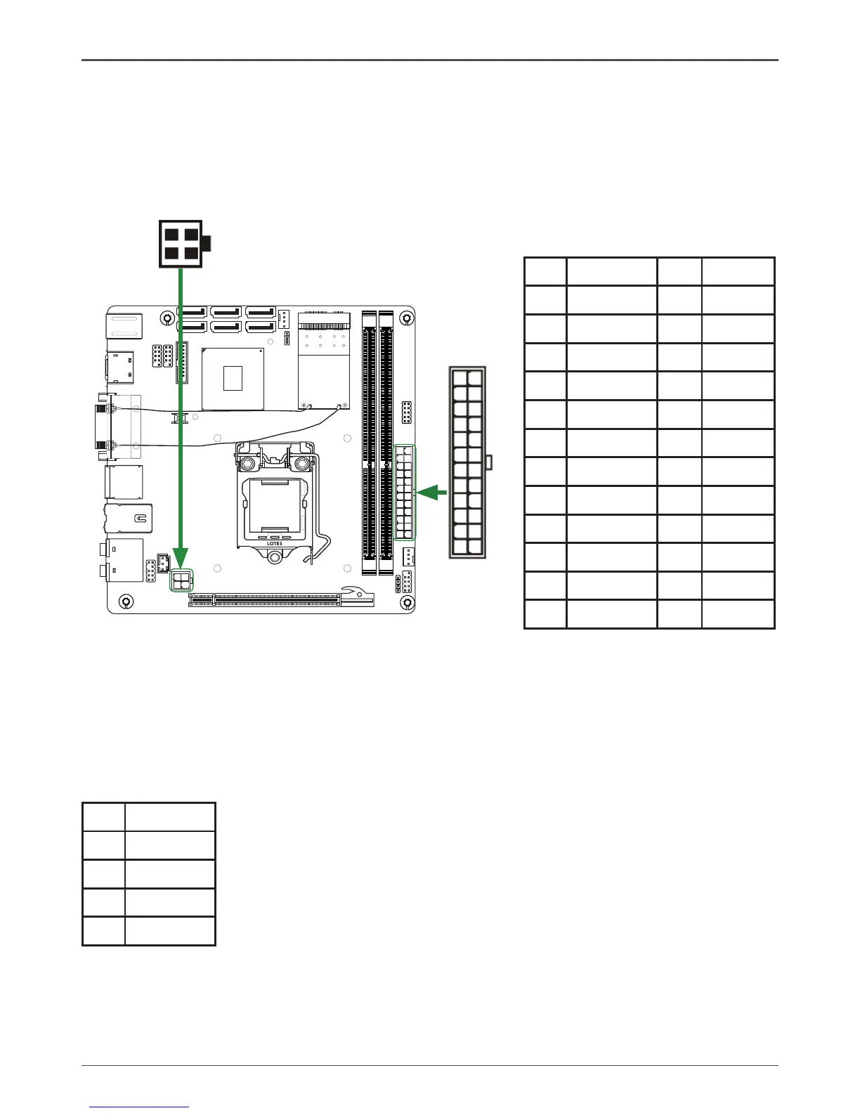
24-pin ATX Power Connector-PW1
PW1 is the main power supply connector. Make sure that the power supply cable and pins are
properly aligned with the connector on the motherboard. Firmly plug the power supply cable into
the connector and make sure it is secure.
PW1-Pin Denition
Pin Signal Pin Signal
1 +3.3V 13 +3.3V
2 +3.3V 14 -12V
3 GND 15 GND
4 +5V 16 PS_ON
5 GND 17 GND
6 +5V 18 GND
7 GND 19 GND
8 PWROK 20 -5V
9 +5V_AUX 21 +5V
10 +12V 22 +5V
11 +12V 23 +5V
12 +3.3V 24 GND
4-pin ATX_12V power connector-PW2
PW2, the 4-pin ATX 12V power connector, is used to provide power to the CPU. Align the pins to
the connector and press rmly until seated.
PW2-Pin Denition
Pin Signal
1 GND
2 GND
3 +12V
4 +12V
120
240
121
120
240
121
1.5V
1.5V
 Loading...