Hardware Installation
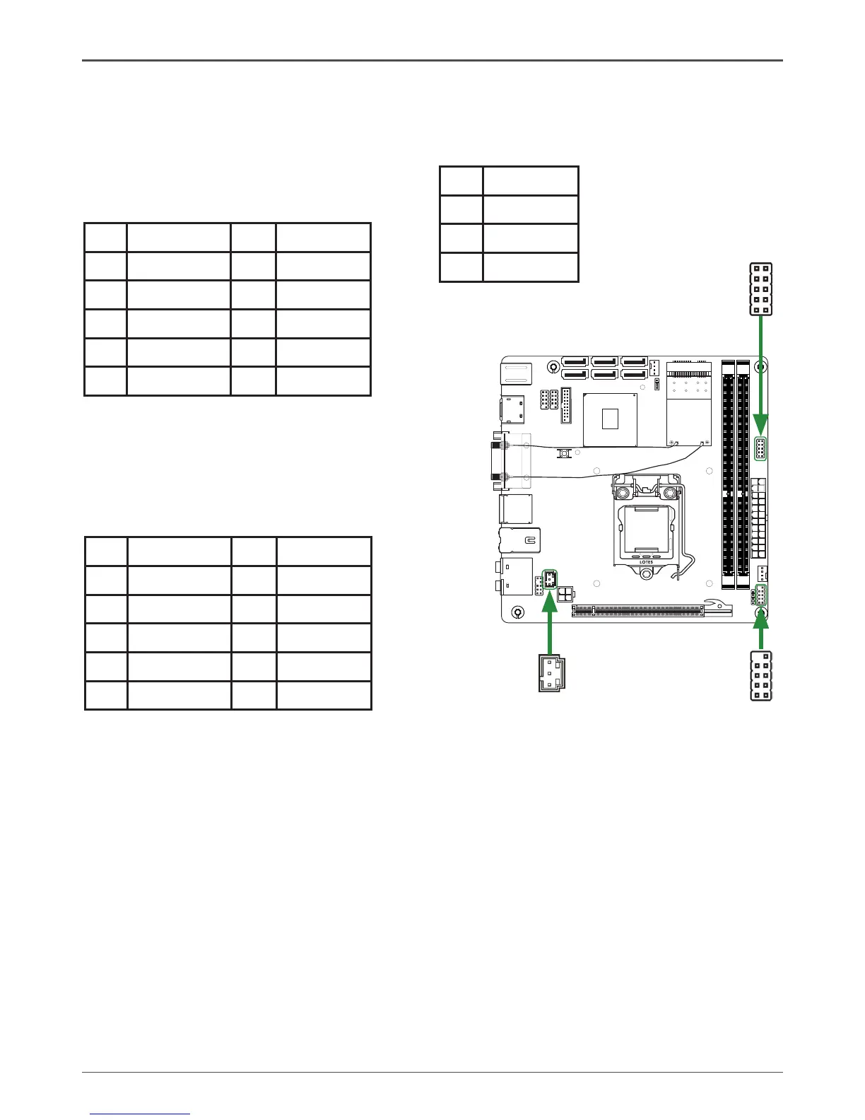
SPDIF-Out Header-CN5
This header provides a SPDIF (Sony/Philips Digital Interface) output to digital multimedia
device through coaxial connector.
CN5 - Pin Denition
Pin Signal
1 GND
2 SPDIF-out
3 VCC
q PWRLED
Attach the front panel power LED cable to these two pins of the connector. The Power LED
indicates the system’s status.
q PWR SW
Attach the power button cable from the case to these two pins. Pressing the power button
on the front panel turns the system on and off rather than using the power supply button.
q HDD LED
Attach the hard disk drive indicator LED cable to these two pins. The HDD indicator LED
indicates the activity status of the hard disks.
q RST SW
Attach the Reset switch cable from the front panel of the case to these two pins. The system
restarts when the RESET switch is pressed.
Note: Some chassis do not have all four cables. Be sure to match the name on the
connectors to the corresponding pins.
Front panel header-FP1
The front panel header on this motherboard is
one connector used to connect the following four
cables :
CN5
1
120
240
121
120
240
121
1.5V
1.5V
 Loading...