Installation | Gateway 400 User Guide
17
Step 4 Connection of telephone system or telephones.
The following figures illustrate the various configuration scenarios for the S
0
ports on the Gateway
400 depending on the telephony hardware used:
Only point-to-point connection
Only point-to-multipoint connection
Mixed operation of point-to-point and point-to-multipoint connections
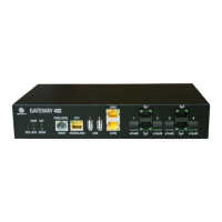
Connect your telephone system or telephones to the sockets S
0
1 to S
0
4 or the clamps 1 to 4 (a1b
a2b). See "Installation diagram for S0 bus" on page 18.
Figure 1 Installation diagram for a point-to-point connection
Note
The ISDN interfaces of the Gateway 400 support the Restricted Power Mode.
This may reduce the functionality of ISDN telephones (e.g., no permanent display) or
cause some telephones to not behave as expected (e.g., signaling of all incoming calls,
regardless of the configured MSN). If necessary, connect an ISDN bus power supply.
 Loading...
