2 EASY
1) Master Card Setting(Reserve)
2) Add Card Setting(Reserve)
2) Delete Card Setting(Reserve)
• Combination With Keypad & TFT Modules
• Combination With Keypad Module
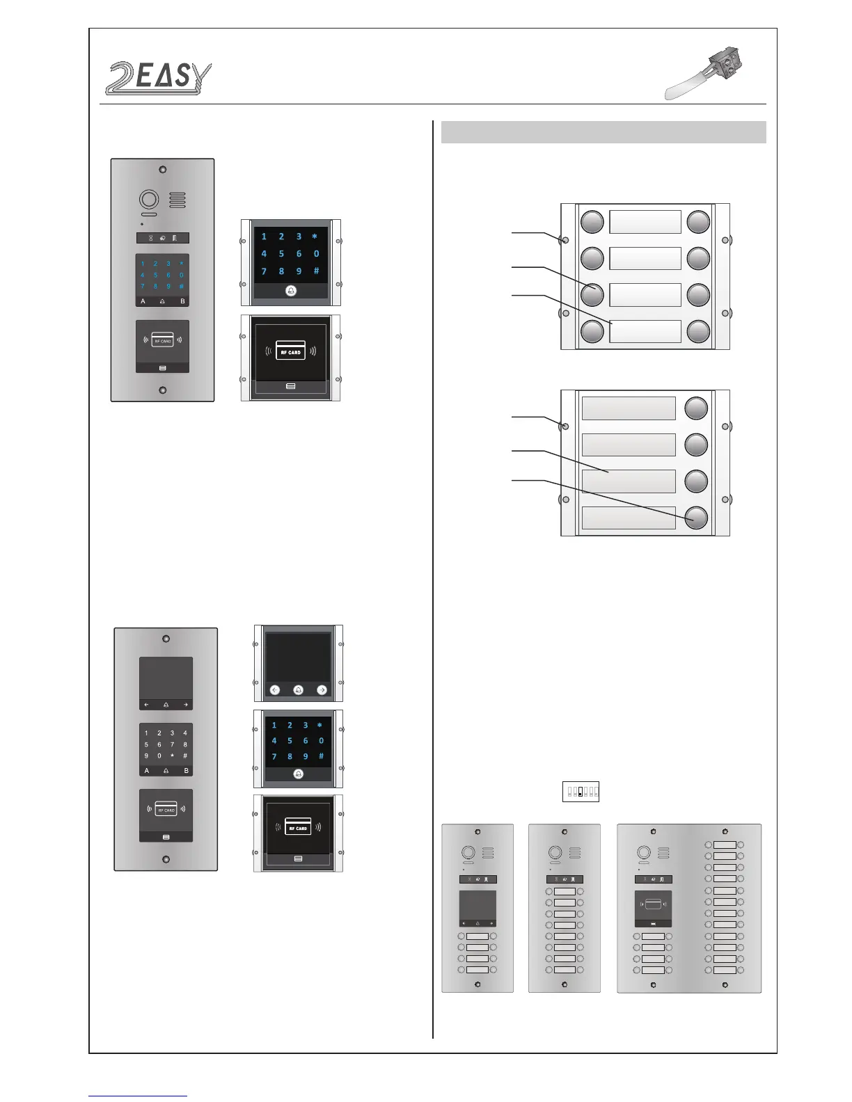
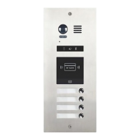
MODULES
CALL BUTTON MODULE
1. Parts and functions
2. Call codes
Call button
Call button
Name plate
Name plate
Double row call button module
Single row call button module
Mounting
screw
Mounting
screw
The DMR21 automatically assigns the call codes to the connected
module’s buttons. Regardless of the structure of the call button mod-
ule, the button numbers are listed from the top to bottom and from
left to right (in the case of double row buttons):
In the case of double row buttons:
* Examples:
01 02
03 04
05 06
07 08
RF CARD
01 02
03 04
05 06
07 08
09 10
11 12
13 14
15 16
09 10
11 12
13 14
15 16
17 18
19 20
21 22
23 24
25 26
27 28
29 30
31 32
01 02
03 04
05 06
07 08
• DIP3 switch set Off
1 2 3 4 5 6
ON
DMR21 Technical Manual-14-