Installation manual 2N® IP Force
•
•
•
•
•
•
•
•
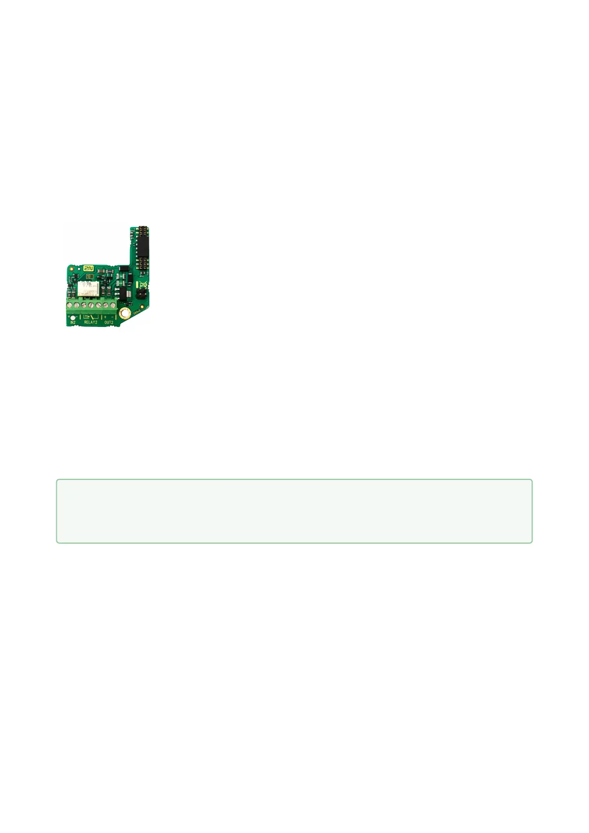
Additional Switch
TheAdditional Switch(Part No.9151010)is used for extending the number
of inputs/outputs.This extending module is intended for mounting into
the2N
®
IP Forcemain unitand is compatible with the basic units with Part
No. 915110xxxxx. If the Additional Switch is installed, it is not possible to
install Internal RFID Card Reader.
Function:
The2N
®
IP ForceAdditional Switch adds two additional switches, one logical
input and a tamperswitch to the2N
®
IP Forcebasic unit. The purpose of the
tamper switch is tosignal any unauthorised opening of the intercom (to
prevent a theft, e.g.). It is recommended to use the tamper switch.
Specifications version 5:
IN2 terminals for input in passive / active mode (-30 V to +30 V DC)
OFF = open OR UIN > 1.5 V
ON = closed contact OR UIN < 1.5 V
RELAY2 terminals 30 V/1 A AC/DC NO/NC contact
OUT2 active output: 12 V/600 mA DC
Tamper switch input (X2): 24 V/50 mA AC/DC
Specifications version 4 a lower:
Passive switch: NO and NC contacts, up to 30 V / 1 A AC/DC
Active switch output: 9 V (Using PoE) or power supply voltage minus 1 V, from 9 to 13 V max. 700 mA DC
•
Tip
FAQ: Tamper switch - How to install it into the 2N
®
IP Force