25
3B6 Operator Manual
O 0 1 2 3 4 567890123
* * * * * ---------1
P08
Digital Outputs (O)
The upper row indicates the Output number, while the lower row indicates its status.
The symbol “*” means active Output, the symbol “-” means non active Output .
0:LMI SHUT-OFF: “*” It happens when overload, or an alarm are active.
1: EXTERNAL BUZZER “*” Active when overload or alarm/warning condition is active
2: RIGHT SHUT-OFF : “*” It happens when the rotation clockwise is not allowed
3: LEFT SHUT-OFF: “*” It happens when the rotation counter-clockwise is not allowed
4: N/A
5: N/A
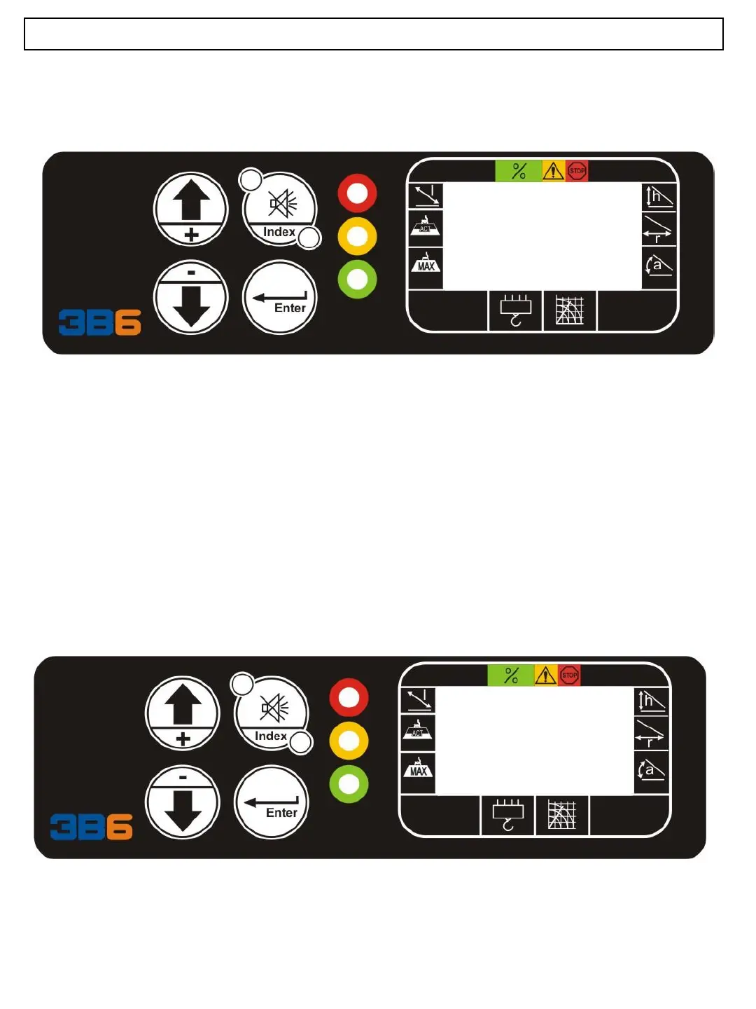
AUTO DIAGNOSTIC
Digital Output Signals
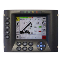
AUTO DIAGNOSTIC
Cable Reel Signals
Value from Cable Reel
The displayed parameters are as follows:
A XXXX : Value of the angle sensor (A channel) in Bits; between 0 and 1023 (*)
L XXXX : Value of the length sensor (A channel) in Bits; between 0 and 1023 (*)
a XXXX : Value of the angle sensor (B channel) in Bits; between 0 and 1023 (*)
l XXXX : Value of the length sensor (B channel) in Bits; between 0 and 1023 (*)
A XXXX B XXXX
a XXXX b XXXX
PO9