Do you have a question about the 3B6 SLIM and is the answer not in the manual?
Provides an overview of the SLIM system and critical safety warnings for operation.
Details the manufacturer's warranty against defects, limitations, and exclusions.
Identifies system components and their connections as shown in the layout diagram.
Describes key system components and their physical locations on the crane.
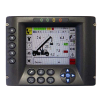
Explains the LCD bar and colored LED status indicators on the SLIM display.
Details parameters like Actual Load, Max Capacity, Radius, Length, Angle, and Parts of Line.
Guides through initial power-up, self-test, crane setup, and operating mode selection.
Describes various operating modes, including Rigging & Travel mode details.
Explains preset range limiting and warning codes for rotation limits.
Details how to set angle, radius, and height limits for the virtual wall feature.
Explains resetting specific limits or disabling all virtual wall features.
Details how to adjust the display contrast using the pushbuttons.
Notes that language and unit settings are for installer configuration only.
Lists warning codes, their causes, and recommended actions or solutions.
Details alarms related to memory, angle, and length sensors, and their solutions.
Details alarms for pressure sensors, shutoff, WDO, CRC errors, and CANBUS.
Details alarms related to A2B conditions, overload SWL, bypass, and rotation sensor issues.
Explains geometrical parameters like load, angle, length, and radius displayed during diagnostics.
Explains parameters related to main and compensation cylinder pressures shown in hydraulic data.
Details angle and length values, including differences, shown in diagnostic modes.
Explains the status of digital inputs like A2B and proximity switches.
Lists analog sensor signal values for pressure, angle, and length in bits.
Explains the status of external digital inputs and their role in selecting operating modes.
Details the status of digital outputs like LMI shut-off and external buzzer.
Provides values for angle and length sensors from the cable reel.
Displays rotation sensor values (channels A/B or 1/2) in degrees.
Guides on checking status master, parameters, flags, inputs, and system variables.
Illustrates wiring connections for main system components and connectors.
| Screen Size | 23.8 inches |
|---|---|
| Resolution | 1920 x 1080 (Full HD) |
| Aspect Ratio | 16:9 |
| Panel Type | IPS |
| Response Time | 5 ms |
| Brightness | 250 cd/m² |
| Contrast Ratio | 1000:1 |
| Color Gamut | 72% NTSC |
| Ports | HDMI, VGA |
| Viewing Angle | 178° (H) / 178° (V) |