32 CHAPTER 2: OPTIMIZING BANDWIDTH
Aggregated Link
Example
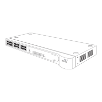
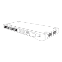
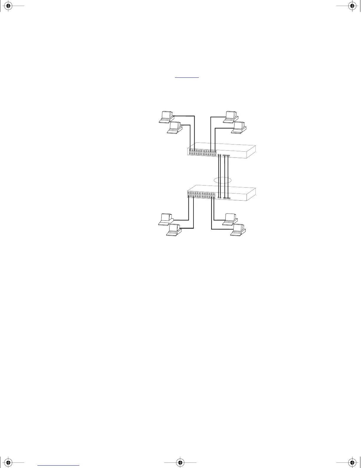
The example shown in Figure 5 illustrates an 4 Gbps aggregated link
between two Switch units.
Figure 5 A 4 Gbps aggregated link between two Switch units
To set up this configuration:
1 Add the 1000BASE-T ports on the upper unit to the aggregated link.
2 Add the 1000BASE-T ports on the lower unit to the aggregated link.
3 Add the SFP ports on the upper unit to the aggregated link.
4 Add the SFP ports on the lower unit to the aggregated link.
5 Connect the 1000BASE-T port marked ‘Up’ on the upper Switch to the
1000BASE-T port marked ‘Up’ on the lower Switch.
6 Connect the 1000BASE-T port marked ‘Down’ on the upper Switch to
the 1000BASE-T port marked ‘Down’ on the lower Switch.
7 Connect the SFP port marked ‘27’ on the upper Switch to the SFP port
marked ‘27’ on the lower Switch.
8 Connect the SFP port marked ‘28’ on the upper Switch to the SFP port
marked ‘28’ on the lower Switch.
Switch 4200 28-Port
4 Gbps Aggregated Link
Switch 4200 28-Port
dua1730-0bAA03.book Page 32 Monday, July 11, 2005 11:14 AM