LEDs of Switch 4500G 24-Port and Switch 4500G 48-Port Switch 13
Figure 4 describes the rear panel of the Switch 4500G 48-Port unit.
Figure 4 Switch 4500G 48-Port—rear panel
LEDs of Switch
4500G 24-Port and
Switch 4500G
48-Port Switch
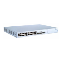
The Switch 4500G 24-Port/Switch 4500G 48-Port Ethernet Switch provides
LEDs on the front panel for your convenience to monitor the switch. 0
describes the meanings of the LEDs. You can use the mode button on the
panel to switch the display mode (rate mode or duplex mode) of LEDs.
Table 3 describes the Switch 4500G 24-Port/Switch 4500G 48-Port Switch
LEDs.
(1) AC power input
(3) Grounding terminal (4) Extended slot 1
(5) Extended slot 2
(1)
(2)
(3)
(4)
(5)
(1)
(2)
(3)
(4)
(5)
Table 3 Description on the LEDs of the Switch 4500G 24-Port/Switch
4500G 48-Port Ethernet Switch
LED Label Status Description
Mode LED Mode Rate
mode
Green, ON The port status LEDs are showing
the port rates.
Duplex
mode
Yellow, ON The port status LEDs are showing
the duplex mode of the ports.
Power LED PWR Green, ON The switch starts normally.
Green, blinking (1 Hz) The system is performing power-on
self test (POST).
Red, ON The system fails the POST.
Yellow, blinking (1 Hz) One or more ports fail the POST.
OFF The switch is powered off.