NA - ENG
March 2017
3M-Matic
™
7000a-7000a3 Pro
Page 20
Crank
Assembly
Fig. 7-7A
Compression
Rollers
Fig. 7-7C
Figure 7-7
Upper Tape
Drum Bracket
Fig. 7-7B
Centering
Guide Knobs
Fig. 7-7D
B
D
A
C
7.5 Removal of Plastic Ties
Cut the plastic which attaches the
top head to the frame and remove
the polystyrene blocks (Figure 7-4).
Cut the plastic strap which attaches
the strip and the EMERGENCY
STOP cable to frame
(Figure 7-5).
Cut the plastic ties holding lower
taping head in position (Figure 7-6).
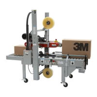
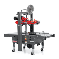
7.6 Assembly Completion
1. Handle - Remove handle from
shipping position and reinstall
in operational position -
(Figure 7-7A).
2. Tape Drum Bracket - Install upper
tape drum bracket on top cross
bar as shown (Figure 7-7B).
3. Compression Rollers - For
shipping purposes, Compression
Rollers are packaged upside down.
Flip Rollers over and mount using
provided hardware (Figure 7-7C).
4. Centering Guides - The Box
Centering Knobs are located in
the Tool Kit Box. Install Knobs on
Centering Guides (Figure 7-7D).
Figure 7-5
Figure 7-6
Figure 7-4
7. Installation (continued)
 Loading...