NA - ENG
March 2017
3M-Matic
™
7000a-7000a3 Pro
Page 28
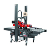
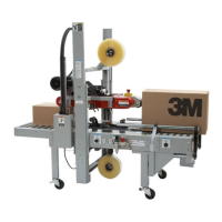
12.1 Operator’s Correct Working
Position and Operational Flow
(Figure 12-1).
Once the box has been lled,
close its top " aps and push it
between the top and bottom
drive belts. Always keep hands
in position as shown in Figure 12-2.
The box will be automatically
sealed with adhesive tape on
the top and bottom box seams.
Then the box will be expelled on
the exit conveyor.
12.2 Starting the Machine
Important: Before starting the
machine, verify that no
tools or other objects
are on conveyor bed.
Turn the main switch ON (I)
after
the EMERGENCY BUTTON is
released (Figure 12-3).
12.3 Starting Production
After having adjusted the machine
according to the box dimensions
(height-width), let the machine run
without cartons and check its
safety devices. Then start the
working cycle.
12.4 Tape Replacement and Threading
Skill 1 - Operator
See Manual 2 or 3: AccuGlide™ 3
High Speed 2 Inch or 3 Inch
Taping Heads.
Press the LATCHING EMERGENCY
STOP BUTTON.
12.5 Box Size Adjustment
Repeat all operations shown in
Section 11 - Set-Up and
Adjustments.
12.6 Cleaning
Before carrying out any cleaning
or maintenance operation, stop
the machine by turning OFF (O)
switch on the main and disconnect
electric power (Figure 12-3).
12.7 Table of Operation Adjustments -
Operator Quali cations
1 Tape loading and threading 1
2 Tape web alignment 1
3 Adjustment of one way tension roller 1
4 Adjustment to box size (H and W) 1
5 Top " ap compression rollers 1
6 Adjustment of tape applying spring 1
7 Conveyor bed height adjustment 1
8 Special Adjustment-Changing tape leg length 2
9 Special Adjustment-Column re-positioning 2
12.8 Safety Devices Inspection
1. Taping units blade guard
2. Latching emergency stop button
3. STOP (OFF) (O) main switch
Figure 12-1
Hand
Position
Figure 12-2
Figure 12-3
12. Operation
 Loading...