27
1. Electrical/Pneumatic "On/Off" Switch
The switch box houses an under voltage motor
protection release circuit breaker that supplies
AC power to the Electrical Control Box .
The Circuit Breaker is preset and requires no
further maintenance. If circuit is overloaded and
trips, unplug machine from power source:
a) Determine and correct cause of overload.
b) Reconnect machine to power source.
c) Turn "On/Off" Switch "On".
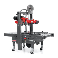
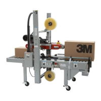
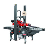
Refer to Figure 7-13 below to acquaint yourself with the various components and controls of the case sealer.
Also see component locations in Section 3 and Manual 2 and Manual 3 for taping head components.
7-INSTALLATION AND SET-UP (continued)
7.15 Controls, Valves, and Switch Locations
Note:
Function of these Controls are
Explained Below.
9
12
10
11
11
8
2
7
1
6
5
4
3
Mechanical Latch,
Upper Drive Assembly
Main Air Pressure
Gauge
Push Button Station
"Start/Stop"
Main Air On/Off Valve/
Pressure Regulator/Filter/
Exhaust Valve
Air Pressure Regulator,
Upper Drive Assembly Pneumatic Force
Electrical/Pneumatic "On/Off" Switch
Electrical Control Box
Air Pressure Regulator,
Centering Guide Force
Proximity Sensor -
Box Centering Guides
Upper Drive
Raising Actuator
(with Proximity Sensor)
Emergency
Stop Switch
Upper Drive
Pressure Gauge
Figure 7-13 Controls, Valves and Switches
2. Main Air "On/Off" Valve/Pressure Regulator/
Filter/Exhaust Valve – Figure 7-14
This set of pneumatic components controls, regulates
and f lters plant air supply to the two separate control
circuits of the case sealer.
"On/Off" Valve – "On" turn to "SUP" – "Off" turn to
"EXH". Note – Turning air supply "Off" automatically
bleeds air pressure from the case sealer air circuits
(continued on next page).
Important: Always turn the air "Off" when
machine is not in use, when servicing
the machine, or when connecting or
disconnecting air supply line.
Figure 7-14
7000r-7000r3 Pro - NA
2014 June
Filter
Down
to Lock
Solenoid
Exhaust
Valve
Up to
Adjust
Air Supply
Connector
Air On/Off
Valve
Regulator
1
 Loading...