Specifications
Section 3
Page 70
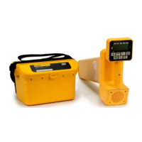
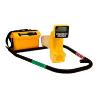
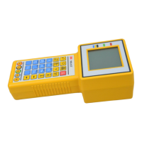
2. 945/945M Subscriber Loop Tester
A. Measurements
Function Range Resolution Accuracy
AC Voltage: 0 to 75 VAC 0.1V 0.7V
75 to 250 VAC 1.0V 3%
DC Voltage: 0 to 100 VDC 0.1V 0.5V
100 to 350 VDC 1.0V 3%
DC Current: 0 to 110 mA DC 0.1 mA 0.3 mA
(Zin = 430 ohms)
Resistance
1
: 0 to 100 Mohms 100 ohms 1%
@ 50 kohms @ 50 kohms
Loss: –40 to +10 dBm 0.1 dB 0.2 dB
(Zin = 600 ohms) 200 to 5,000 Hz
Noise Metallic
2
: 10 to 50 dBrnC 0.1 dB 0.5 dB
0 to 10 dBrnC 0.3 dB 2.0 dB
(Zin = 600 ohms)
Noise to
Ground: 40 to 100 dBrnC 0.1 dB 0.5 dB
(Zin = 600 ohms)
Opens
1
:(normal mode)
0 to 9.99 kft 10 ft @ 10 kft +
1%
10k ft to 100 kft 100 ft +1/–10%
0 to 30000 m 3 m @ 500 m 1.5 m ±1%
@ 500 m
Tolerance to Leakage,
Normal Mode: >15 kohm to ground / 190 kohm to battery
Opens
1
:(special mode)
0 to 999 ft 1 ft +
1%
1 kft to 10 kft 100 ft @ 10 kft +1/–10%
0 to 30000 m 3 m @ 500 m 6m ±1%
@ 500 m
Tolerance to Leakage,
Special Mode: >1200 ohms to ground/18 kohms to battery
Frequency
Measurement: 20 to 20,000 Hz 1 Hz 2 Hz
during Loss, single frequency only
Ground
Resistance: 0 to 500 ohms 1 Ohm 3 ohms
Loop and C.O.
Resistance: 0 to 5000 ohms 1 Ohm +
10% +
50 ohms
(read through the REG key assuming on-hook resistance is known)
Note:
1
Perform a self-calibration before taking the readings.
2
C-message specifications have an additional frequency-
dependent tolerance. Refer to “IEEE Standard 743–
1984.” The 945/945M far exceeds these tolerances. For
most frequencies the total error is less than 0.7 dB.