21
LOW PROFILE SIDE WALL VENT TERMINATION
The Low Prole termination is certied to be used on PDV installations
only. These instructions are to be followed in conjunction with the
installation guide provided with the System 636 components or at
www.ipexna.com/resources/technical-library.
Table 9. Low Prole Termination Kits
Description Pipe O.D. P/N
Kit, Low Prole Termination 2” 100187903
Kit, Low Prole Termination 3” 100187887
All termination kits must be located and installed in accordance
with local building code and the current edition of the
Natural Gas and
Propane Installation Code B149.1
.
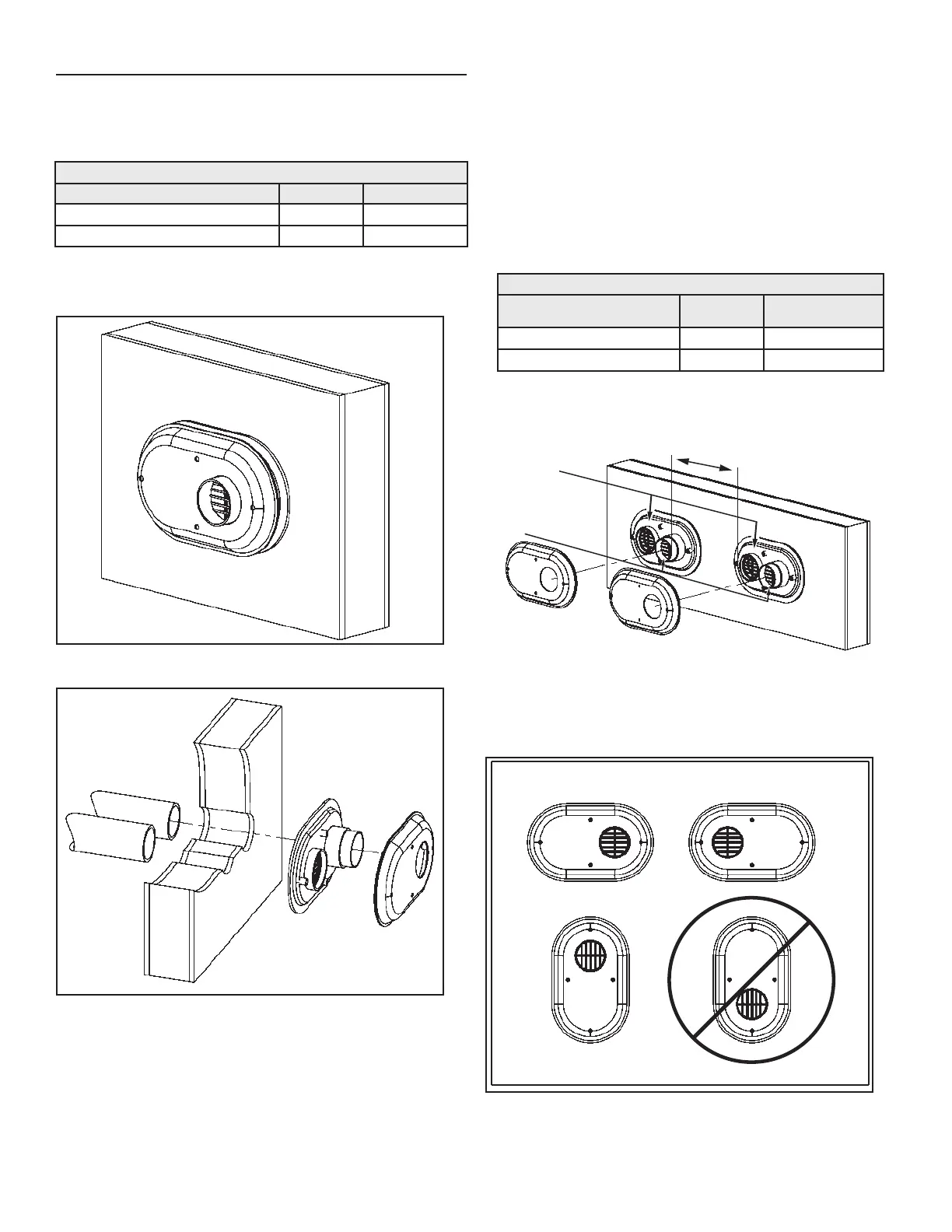
LOW PROFILE
TERMINATION
EXHAUST
Figure 19. Low Profile Sidewall Termination
EXHAUST
PIPING
INTAKE
PIPING
VENT
BASE
VENT
CAP
Figure 20. Low Profile Termination Installation
INSTALLATION PROCEDURE
1. Once the proper location has been determined, cut 2 holes in
the wall large enough to accommodate the pipe. Pipe diameters
and distance between hole centers can be found in
Table 10
.
2. Slide both the intake and exhaust pipes through the holes.
Solvent cement both pipes to the base of the vent termination
kit, follow the solvent cementing procedures outlined in the
System 636 Installation Guide.
3. To fasten the Base to the wall, use the supplied screws and
anchors. A 5 mm (3/16”) hole, 30 mm (1-3/16”) deep, will need
to be drilled for the anchors. Locate the anchor hole using the
base as a template.
4. Screw the Cap to the Base using the supplied screws.
5. Once the vent termination and pipes are secured, the wall
penetrations will need to be sealed from the interior using a
PVC-compatible sealant material.
Table 10. Low Prole Termination Kits
Description Pipe O.D. Hole Spacing (ctr
to ctr)
2” Flush Mount Vent Kit 2.38” 142 mm (5.6”)
3” Flush Mount Vent Kit 3.5” 142 mm (5.6”)
Intake
Exhaust
300 mm (12”) MIN. BETWEEN EDGE OF THE
EXHAUST OUTLET AND ADJACENT AIR INTAKE
Figure 21. Adjacent Low Profile Termination Clearances
Figure 22
illustrates the possible orientations of the Low Prole
termination. Note that only three of the orientations are allowed.
Figure 22. Possible Orientations of Low Profile Terminations

 Loading...