34
POWER FLUCTUATIONS AND ELECTRICAL NOISE
The water heater’s control system requires a source of stable
clean electricity for proper operation. Connecting the water heater
to a branch circuit that is subject to uctuations in voltage level or
electrical line noise such as EMI (electro-magnetic interference) or
RFI (radio frequency interference) may cause erratic control system
operation and malfunction.
A high quality power supply lter/suppressor must be installed if the
above conditions exist. Call the technical support phone number for
more information.
Note: Malfunctions caused by the power supply and the costs to
install the power supply lters are not covered under the
limited warranty.
ELECTRICAL WIRING
If you lack the necessary skills required to properly install the
electrical wiring to this water heater, do not proceed but have a
qualied electrician perform the installation. See
Electrical Supply
(page 33) for additional requirements.
When making the electrical connections, always make sure:
• The voltage and frequency must correspond to that specied
on the water heater data plate on the front of the water heater.
• The electrical supply has the proper overload fuse or breaker
protection. The heater draws less than 10 amps.
• Wire sizes, connections and conduits comply with all applicable
codes.
• The water heater and electrical supply are properly grounded.
• This water heater must be “hard-wired” do not use an extension
cord to supply electrical power to this water heater.
Note: The wiring diagram can be found in
Diagrams
(page 53).
Always reference the wiring diagram(s) for the correct
electrical connections.
When installing the electrical wiring to the water heater:
1. Shut o the power at the electrical service box.
2. Loosen the screws securing the access panel to the electrical
compartment. (The electrical wiring diagram for all models can be
found on the inside of the access panel at the base of the water
heater. Set the access panel aside.
3. Connect the electrical supply to the water heater in accordance
with local utility requirements and codes. Use only a dedicated
electrical circuit containing a properly sized fuse or circuit breaker.
Maximum overload protection should not exceed 15 amperes.
4. Connect this circuit (directly from the electrical service box) to an
electrical disconnect switch.
5. Ground the water heater by connecting the electrical service
ground wire to the green ground wire (provided).
Note: The power supply to this water heater must be properly
polarized, [120 volts from the hot lead (black) to ground and
0 volts from the neutral lead (white) to ground] otherwise, the
unit will not operate.
6. After making all electrical connections, completely ll the tank with
water and check all connections for leaks. Open the nearest hot
water faucet and let it run for 3 minutes to purge the water lines of
air and sediment and to ensure complete lling of the tank. The
electrical power may then be turned on. See
Start Up
(page 42).
GAS SUPPLY SYSTEMS
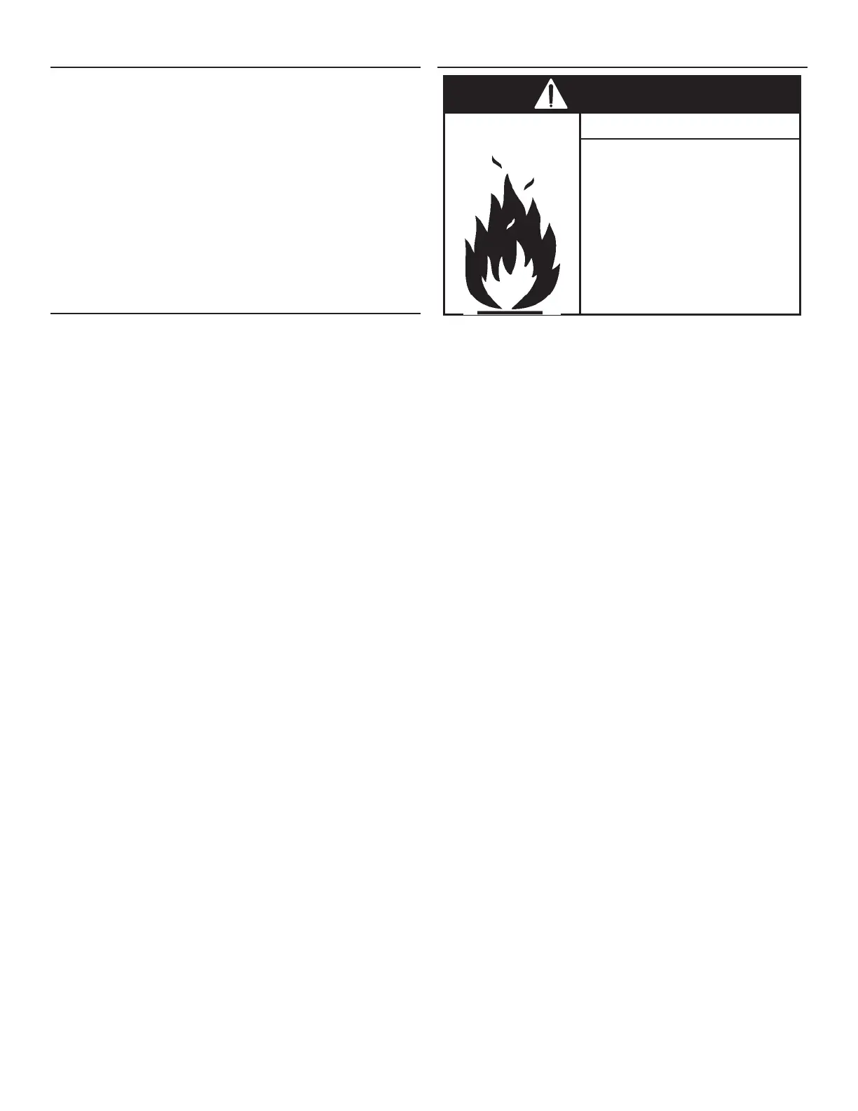
• Do not use water heater with
any gas other than the gas
shown on the rating plate.
• Excessive pressure to gas
control valve can cause serious
injury or death.
• Turn off gas lines during
installation.
• Contact qualified installer or
service agency.
Fire and Explosion Hazard
Low pressure building gas supply systems are dened as those
systems that cannot under any circumstances exceed 14” w.c.
(3.5 kPa). These systems do not require pressure regulation.
Measurements should be taken to insure that gas pressures are
stable and fall within the requirements stated on the water heater
rating plate. Readings should be taken with all gas burning equipment
o (static pressure) and with all gas burning equipment running at
maximum rate (dynamic pressure). The gas supply pressure must
be stable within 1.5” w.c. (0.37 kPa) from static to dynamic pressure
to provide good performance. Pressure drops that exceed 1.5” w.c.
(0.37 kPa) may cause rough starting, noisy combustion or nuisance
outages. Increases or spikes in static pressure during o cycles may
cause failure to ignite or in severe cases damage to water heater
gas control valves. If your low pressure system does NOT meet
these requirements, the installer is responsible for the corrections.
High pressure building supply systems use pressures that exceed
14” w.c. (3.5 kPa). These systems must use eld supplied regulators
to lower the gas pressure to less than 14” w.c. (3.5 kPa). Water
heaters require gas regulators that are properly sized for the water
heater input and deliver the rating plate specied pressures. Gas
supply systems where pressure exceeds 5 psi (34.4 kPa) often
require multiple regulators to achieve desired pressures. Systems
in excess of 5 psi (34.4 kPa) building pressure should be designed
by gas delivery professionals for best performance. Water heaters
connected to gas supply systems that exceed 14” w.c. (3.5 kPa) at
any time must be equipped with a gas supply regulator.
All models require a minimum gas supply pressure of 3.5” w.c. (0.87
kPa) for natural gas. The minimum supply pressure is measured
while gas is not owing (static pressure) AND while gas is owing
(dynamic pressure). The supply pressure (static and dynamic)
should never fall below 3.5” w.c. (0.87 kPa) for natural gas. The
supply pressure should be measured with all gas red water heaters
connected to the common main ring at full capacity. If the supply
pressure drops more than 1.5” w.c. (0.37 kPa) as gas begins to ow
to the water heater then the supply gas system including the gas
line and/or the gas regulator may be restricted or undersized. See
Gas Supply Regulator
(page 35) and
Gas Line Installation
(page 35).
The gas control valve on all models has a maximum gas supply
pressure limit of 14” w.c. (3.48 kPa) The maximum supply pressure
is measured while gas is not owing (static pressure)
AND
while gas
is owing (dynamic pressure).

 Loading...