26
TERMINATION CLEARANCES OTHER THAN SIDEWALL DIRECT VENT
Fixed
Closed
Operable
Fixed
closed
Operable
B
V
V
V
V
V
V
V
V
C
B
B
X
A
M
K
Regulator vent outlet
In the event no
regulator is present,
H and I can be
disregarded
.
V
Legend:
= Vent terminal
X
= Air supply inlet
= Area where terminal is not permitted
B
B
J
F
X
B
L
E
D
Inside
corner detail
V
A
G
H
15 ft
I
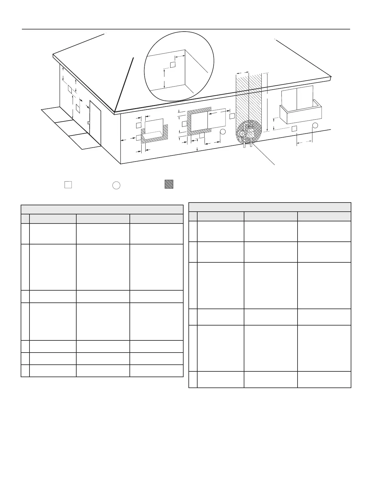
Figure 30. Other than Direct Vent Using Outside Air
Table 15. Termination Clearances for Sidewall Direct Vent
Type of Clearance
Canadian Installations
1
US Installations
2
A Clearance above
grade, veranda,
porch, deck or
balcony
12 inches (30 cm) 12 inches (30 cm)
B Clearance to window
or door that may be
opened
• 6 in (15 cm) for appli-
ances ≤ 10,000 Btuh
(3 kW)
• 12 in (30 cm) for appli-
ances > 10,000 Btuh
(3 kW) and ≤ 100,000
Btuh (30 kW),
• 36 in (91 cm) for appli-
ances > 100,000 Btuh
(30 kW)
4 feet (1.2 m) below or to
side of opening;
1 foot (30 cm) above
opening
C Clearance to perma-
nently closed window
6 inches (15 cm)* 6 inches (15 cm)*
D Vertical clearance
to ventilated sot
located above the
terminal within a
horizontal distance of
2 feet (61 cm) from
the center line of the
terminal
12 inches (30 cm) 12 inches (30 cm)
E Clearance to unventi-
lated sot
12 inches (30 cm) 12 inches (30 cm)
F Clearance to outside
corner
2 feet (60 cm)* 2 feet (60 cm)*
G Clearance to inside
corner
18 inches (45 cm)* 18 inches (45 cm)*
Table 15. Termination Clearances for Sidewall Direct Vent
Type of Clearance
Canadian Installations
1
US Installations
2
H Clearance to each
side of center line ex-
tended above meter/
regulator assembly
3 ft (91 cm) within a
height 15 ft (4.6 m)
Clearance in accordance
with local installation
codes and the require-
ments of the gas supplier
I Clearance to service
regulator vent outlet
3 ft (1.83 m) Clearance in accordance
with local installation
codes and the require-
ments of the gas supplier
J Clearance to a non
mechanical air supply
inlet into building or
combustion air inlet to
any other appliance
• 6 in (15 cm) for appli-
ances ≤ 10,000 Btuh
(3 kW)
• 12 in (30 cm) for appli-
ances > 10,000 Btuh
(3 kW) and ≤ 100,000
Btuh (30 kW)
• 36 in (91 cm) for appli-
ances >100,000 Btuh
(30 kW)
4 feet (1.2 m) below or to
side of opening;
1 foot (30 cm) above
opening
K Clearance to a
mechanical air supply
inlet
6 feet (1.83 m) 3 feet (91 cm) above
if within 10 feet (3 m)
horizontally
L Clearance above
paved sidewalk or
paved driveway
located on public
property
7 feet (2.13 m)† 7 ft (2.13 m) for me-
chanical draft systems
(Category I appliances);
vents for Category II and
IV appliances cannot
be located above public
walkways or other areas
where condensate or va-
por can cause a nuisance
or hazard
M Clearance under
veranda, porch, deck,
or balcony
12 inches (30 cm) ‡ 12 inches (30 cm) ‡
1 In accordance with the current
CSA B149.1, Natural Gas and Propane Installation Code
.
2 In accordance with the current
ANSI Z223.1/NFPA 54, National Fuel Gas Code
.
† A vent shall not terminate directly above a sidewalk or paved driveway that is
located between two single family dwellings and serves both dwellings where it may
cause hazardous frost or ice accumulations on adjacent property surfaces.
‡ Permitted only if veranda, porch, deck, or balcony is fully open on a minimum of
two sides beneath the oor.

 Loading...