36
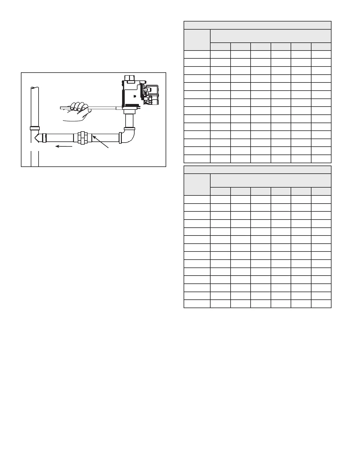
4. Install a ground union between the water heater and the manual
shut-o valve. This is to allow easy servicing. See
Figure 47
.
5. Turn the gas supply on and check for leaks. See
Figure 47
. Use a
chloride-free soap and water solution (bubbles forming indicate
a leak) or other approved method.
Note: Units with inputs of 175,000 BTU/hr or above must have a
minimum of 3/4” NPT gas pipe supplied to the water heater.
BLACK PIPE
INSTALLATIONS
SEDIMENT
TRAP
GAS
CONTROL
VALVE
GROUND
JOINT UNION
(OPTIONAL)
CAP
3” MIN.
Figure 41. Black Pipe to Gas Valve
Note: Always secure the square on the gas valve base with a
suitable wrench when tightening or loosening the gas piping.
GAS LINE SIZING
Depending on the developed equivalent length and/or the number
of appliances connected to a common main, the size of supply gas
lines may have to be increased.
Size the supply/main gas line(s) in accordance with
Table 18
or
Table 19
.
The values given in
Table 18
or
Table 19
are for straight lengths of
iron pipe at 0.5” W. C. (125 Pa) pressure drop, which is considered
normal for low pressure systems.
Note: Fittings such as elbows and tees will add to the pipe pressure
drop.
Schedule-40 Steel or wrought-iron pipe is the preferred material for
the gas line of this water heater. It is imperative to follow the sizing
recommendations in the latest version of the
National Fuel Gas Code
if corrugated stainless steel tubing (CSST) is used as the gas line
for this water heater.
Table 18. Supply Gas Line Sizing U. S. Units
Length in
Feet
Normal Iron Pipe Sizes (Inches)
Input In Thousands Btu/Hr
1/2” 3/4” 1” 1 1/4” 1 1/2” 2”
10 175 360 680 1400 2100 3960
20 120 250 485 950 1460 2750
30 97 200 375 770 1180 2200
40 82 170 320 660 990 1900
50 73 151 285 580 900 1680
60 66 138 260 530 810 1520
70 61 125 240 490 750 1400
80 57 118 220 460 690 1300
90 53 110 205 430 650 1220
100 50 103 195 400 620 1150
125 44 93 175 360 550 1020
150 40 84 160 325 500 950
175 37 77 145 300 460 850
200 35 72 135 280 430 800
Table 19. Supply Gas Line Sizing Metric Units
Length In
Meters
Normal Iron Pipe Sizes (inches)
Input in kW
1/2” 3/4” 1” 1 1/4” 1 1/2” 2”
3.0 51 105 199 410 615 1160
6.1 35 73 142 278 428 805
9.1 28 59 110 225 346 644
12.2 24 50 94 193 290 556
15.2 21 44 83 170 264 492
18.3 19 40 76 155 237 445
21.3 18 37 70 143 220 410
24.4 17 35 64 135 202 381
27.4 16 32 60 126 190 357
30.5 15 30 57 117 182 337
38.1 13 27 51 105 161 299
45.7 12 25 47 95 146 278
53.3 11 23 42 88 135 249
61.0 10 21 40 82 126 234

 Loading...