TroubleshootingGuide
17|Page
ERRORCODE611[510(T‐D2)],FOURFLA SHES/61[110(T‐KJR2),310(T‐K4)]
ABNORMALFANMOTOR
1) Turnoffpowersupply.
2) Checkfanmotorwiringforanybreakages,burnmarksonthePCboard,ormoisture.Ifmoistureis
found,allowconnectiontocompletelydrybeforeturningpowerbackon.
3) Checkfanhousingforwater.Iffound,pleasedrythefan,thentestheater.
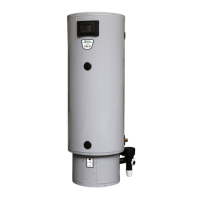
4)
Toremovethefanmotor.
a. Turnoffthepowersupply.
b. Movethecomputerboardoutoftheway.
c. LocatethetwoPhillipsheadscrewsfittedatthetopof
thefanmotortothecombustionchamberbox.Two
holesarelocateddirectlyatthebottomofthe
casethat
lineupwiththetwoscrews.Usingan8”screwdriver,
removethescrews.
d. Slidethefanouttowardstheleft.
e. Ifsignsofwaterareevident,watermayhavedamaged
thefanmotorrequiringreplacement.
5) Ifthe611errorcodestillappearsafterallitemshave
beenchecked,thePCBmayneedreplacement
ERRORCODE651[510(T‐D2)]
ABNORMALFLOWADJUSTMENTVALVE
1) Turnoffpowersupply.
2) Checkthatallwireconnectionsaresecureandfreeof
burns.Theflowadjustmentvalveislocatedbehindthe
computerboardandattachedtothecoldwaterinlet.
3) Checkforwaterleakagefromthevalve.
4) DoavisualinspectionofthePCB.Check
for
connection/breakageofwiresand/orburnmarksonthe
board.PCBmayneedtoberepla ced.
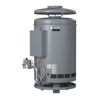
5) Theflowadjustmentvalvemayneedtobecleaned.To
remove,followthestepsbelow:
a. Removethefourwaterwayclipsoneachsideofthe
valves.
b. Slidethevalveupoff
theinletwaterconnection.
c. Checkbothendsofthevalveforsedimentordebris.Useabrushordescalingsolutionto
removethesediment.
d. Re‐installthevalveandclips.
e. Testtheheater.
6) Theflowadjustmentvalvemayneedtobereplacedifthevalvecannotbe
cleaned.
ERRORCODE701[510(T‐D2)],ONEFLASH/70[110(T‐KJR 2),310(T‐K4)]
COMPUTERBOARDFAULT
1) Turnoffthepowersupply.
2) Checkallwireconnectionsandmakesuretheyaresecureandfreeofburnsorcuts.
3) InspectthePCBforconnection/breakageofwiresand/orburnmarksontheboard.
4) Verifythatsupplygaspressureiswithinspecifications.
5) ContacttheTechnicalService
Departmentforfurtherassistance.
Figure13
Figure14