23
MECHANICAL VENTING
SINGLE UNIT INSTALLATION
When mechanical venting of these heaters is desired, the following
kits are available.
Models 120 through the 200/A
A. O. Smith part number 9006015
Models 250/A through the 400/A
A. O. Smith part number 9006016
Where an approved power venter is to be installed to operate in
conjunction with the water heater thermostat, the following codes
must be adhered to. Field wiring should conform to the current
edition of the
National Electrical Code NFPA 70. For Canadian
installations the electrical connections and grounding shall be
done in accordance with the current Natural Gas and Propane
Installation Code CAN/CSA-B149.1 Part 1 and/or local codes.
VENT INSTALLATION
Seal all joints between the power venter and the vent termination.
This is to prevent leakage of exhaust products into the room(s)
due to positive pressure of blower.
The "Sequence of Operation" description will be the same with
mechanical venting except,
When the appliance thermostat calls for heat:
Thermostat contacts "Close" and the power venter blower
(120 VAC) is energized. Sufficient draft must be established for
the "Draft Prover Switch (N.O.)" to "Close". When the draft prover
switch "Closes" the relay coil of the flue damper is energized.
See side wall vent kit installation manual for complete instructions.
MULTIPLE UNIT INSTALLATIONS
For multiple unit installations, contact A.O. Smith Water Products
Company, Technical Support Center at 1-800-527-1953. In
Canada, contact A.O. Smith Enterprises, Ltd. at 1-800-265-8520.
TABLE 5
MANIFOLD GAS PRESSURE IN INCHES
OF WATER COLUMN (ALL MODELS*)
TYPE OF GAS
NATURAL PROPANE
3.5 10.0
Gas pressure specified in Table 5, refer to flow pressure taken at
pressure tap of automatic gas valve while heater is operating.
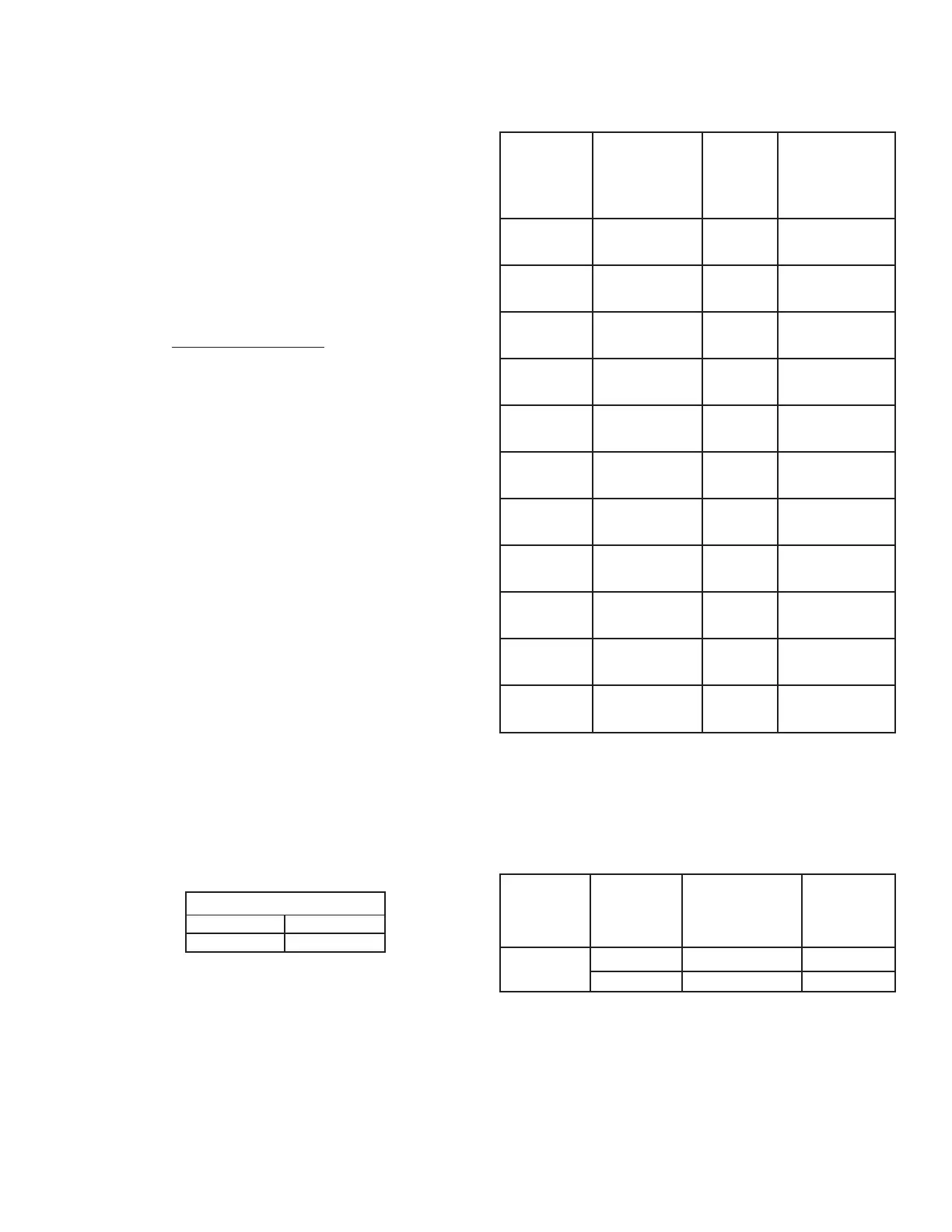
TABLE 6
APPROXIMATE TIME REQUIRED TO CONSUME
1 CU. FT. OF GAS AT FULL CAPACITY
INPUT TYPE BTUH TIME REQ’D
RATE OF PER TO CONSUME
(BTUH) GAS CU. FT. 1 CU. FT.
OF GAS
120,000 NATURAL 1050 31.5 SEC.
PROPANE 2500 75.0 SEC.
154,000 NATURAL 1050 24.5 SEC.
PROPANE 2500 58.4 SEC.
180,000 NATURAL 1050 21.1 SEC.
PROPANE 2500 50.3 SEC.
199,000 NATURAL 1050 19.0 SEC.
PROPANE 2500 47.4 SEC.
250,000 NATURAL 1050 15.1 SEC.
PROPANE 2500 35.3 SEC.
251,000 NATURAL 1050 15.06 SEC.
PROPANE 2500 35.1 SEC.
275,000 NATURAL 1050 13.75 SEC.
PROPANE 2500 32.2 SEC.
305,000 NATURAL 1050 12.4 SEC.
PROPANE 2500 29.5 SEC.
360,000 NATURAL 1050 11.4 SEC.
PROPANE 2500 24.0 SEC.
365,000 NATURAL 1050 10.4 SEC.
PROPANE 2500 24.7 SEC.
390,000 NATURAL 1050 9.5 SEC.
PROPANE 2500 22.6 SEC.
Figures shown are valid for 0-2000 ft.(0-610m) installations. See
“HIGH ALTITUDE INSTALLATIONS” for deration requirements
over 2000 ft.(610m).
TABLE 7
PILOT BURNER INFORMATION
TYPE OF PILOT BURNER RATED
MODEL GAS PART NUMBER ORIFICE
(WITH ORIFICE) SIZE
ALL NATURAL 193314-004 0.018
MODELS PROPANE 193314-003 0.014