13
If a water heater is installed in a closed water system, contact the
water supplier or local plumbing inspector on how to control this
situation.
WATER (POTABLE) HEATING AND
SPACE HEATING
1. All piping components connected to this unit for space heating
applications shall be suitable for use with potable water.
2. Toxic chemicals, such as those used for boiler treatment, shall
NEVER be introduced into this system.
3. This unit may NEVER be connected to any existing heating
system or component(s) previously used with a non-potable
water heating appliance.
4. When the system requires water for space heating at
temperatures higher than required for domestic water
purposes, a tempering valve must be installed. Please refer
to installation diagrams on pages 16 through 21 in this manual
for suggested piping arrangements.
CAUTION
A closed system will exist if a check valve (without bypass),
pressure reducing valve (without bypass), or a water meter (without
bypass) is installed in the cold water line between the water heater
and street main (or well).
Excessive pressure may develop in such closed systems, causing
premature tank failure or intermittent relief valve operation. This
is not a warranty failure. An expansion tank or a similar device
may be required in the inlet supply line between the appliance
and the meter or valve to compensate for the thermal expansion
of the water.
SYSTEM CONNECTIONS
The system installation must conform to these instructions and to
the local code authority having jurisdiction. Good practice requires
that all heavy piping be supported.
THERMOMETERS (Not Supplied)
Thermometers should be obtained and field installed as shown in
the installation diagrams.
Thermometers are installed in the system as a means of detecting
the temperature of the outlet water supply.
RELIEF VALVE
This water heater is equipped with a combination temperature-
pressure relief valve that complies with the standard for relief
valves and automatic gas shut-off devices for hot water supply
system, ANSI Z21.22-CSA 4.4. FOR SAFE OPERATION OF THE
WATER HEATER, THE RELIEF VALVE(S) MUST NOT BE
REMOVED OR PLUGGED.
ASME ratings cover pressure relief capacities. ANSI ratings cover
release rate with temperature actuation.
In addition to the appliance relief valve, each remote storage tank
which may be used in conjunction with this appliance shall also
be installed with a properly sized, rated and approved combination
temperature (ANSI) and pressure (ASME) relief valve(s).
WARNING
THE PURPOSE OF RELIEF VALVE IS TO AVOID EXCESSIVE
PRESSURE OR TEMPERATURE INTO THE STEAM RANGE,
WHICH MAY CAUSE SCALDING AT FIXTURES, TANK
EXPLOSION, SYSTEM OR HEATER DAMAGE. NO VALVE IS
TO BE PLACED BETWEEN THE RELIEF VALVE AND TANK.
Your local code authority may have other specific relief valve
requirements.
A DRAIN LINE MUST BE CONNECTED TO THE RELIEF
VALVE TO DIRECT DISCHARGE TO A SAFE LOCATION TO
AVOID SCALDING OR WATER DAMAGE. THIS LINE MUST
NOT BE REDUCED FROM THE SIZE OF THE VALVE OUTLET
AND MUST NOT CONTAIN VALVES, RESTRICTIONS NOR
SHOULD IT BE LOCATED IN FREEZING AREAS. DO NOT
THREAD OR CAP THE END OF THIS LINE. RESTRICTED
OR BLOCKED DISCHARGE WILL DEFEAT THE PURPOSE
OF THE VALVE AND IS UNSAFE. DISCHARGE LINE SHALL
BE INSTALLED TO ALLOW COMPLETE DRAINAGE OF BOTH
THE VALVE AND LINE.
See SERVICE INFORMATION section for procedure and
precautions.
GAS PIPING
Contact your local gas service company to ensure that adequate
gas service is available and to review applicable installation codes
for your area.
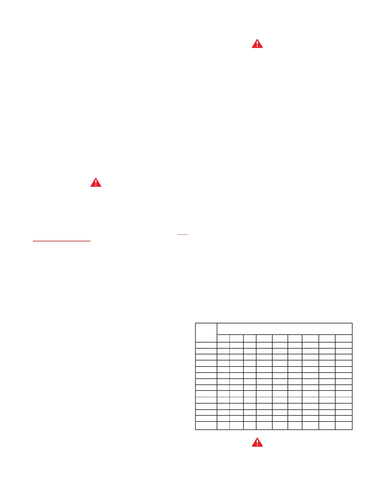
Size the main gas line in accordance with Table 4. The figures
shown are for straight lengths of pipe at 0.5 in. W.C. pressure drop,
which is considered normal for low pressure systems. Note:
Fittings such as elbows, tees and line regulators will add to
the pipe pressure drop. Also refer to the current edition of the
National Fuel Gas Code. For Canadian installations consult
Natural Gas and Propane Installation Code CAN/CSA-B149.1.
TABLE 4 - GAS SUPPLY LINE SIZES (IN INCHES)*
MAXIMUM CAPACITY OF PIPE IN
CUBIC FEET PER HOUR
LENGTH NOMINAL IRON PIPE SIZES (INCHES)
IN
FEET 1/2” 3/4” 1” 1 1/4” 1 1/2” 2” 2 1/2” 3” 4”
10 175 360 680 1400 2100 3960 6300 11000 23000
20 120 250 465 950 1460 2750 4360 7700 15800
30 97 200 375 770 1180 2200 3520 6250 12800
40 82 170 320 660 990 1900 3000 5300 10900
50 73 151 285 580 900 1680 2650 4750 9700
60 66 138 260 530 810 1520 2400 4300 8800
70 61 125 240 490 750 1400 2250 3900 8100
80 57 118 220 460 690 1300 2050 3700 7500
90 53 110 205 430 650 1220 1950 3450 7200
100 50 103 195 400 620 1150 1850 3250 6700
125 44 93 175 360 550 1020 1650 2950 6000
150 40 84 160 325 500 950 1500 2650 5500
175 37 77 145 300 460 850 1370 2450 5000
200 35 72 135 280 430 800 1280 2280 4600
WARNING
THE HEATER IS NOT INTENDED FOR OPERATION AT HIGHER
THAN 14.0" W.C.(3.5 kPa) (1/2 POUND PER SQUARE INCH