Do you have a question about the Aalborg DPC and is the answer not in the manual?
Essential safety precautions to follow during installation.
Specifies maximum operating and differential pressure limits for safe operation.
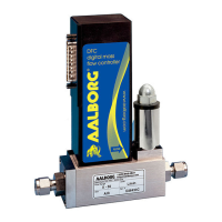
Instructions on how to physically mount the DPC Mass Flow Controller.
Details on connecting the power supply to the DPC controller.
Connecting analog signals for outputting flow data.
Connecting for RS-232 or RS-485 communication.
Lists available accessories for DPC controllers.
Steps for initial setup and powering on the DPC controller.
Navigating and understanding the instrument's process data screens.
Overview of the menu navigation and structure using the local interface.
Methods for entering numerical and tabular data via the interface.
Procedure for changing the program protection password for security.
How to set the instrument's set point and control valve mode.
Selecting the active gas for measurement and configuration.
Configure gas flow alarms, including limits, delays, and actions.
Configure gas pressure alarms, including limits, delays, and actions.
Configure gas temperature alarms, including limits, delays, and actions.
Settings related to the instrument's control valve.
Configuration of how process information is displayed on the OLED screen.
Configuring communication interface type, speed, and address.
Configuring analog output signals (0-5Vdc, 0-10Vdc, 4-20mA).
Setting up custom, user-preset programs for flow control.
Procedure to calibrate the differential pressure sensor to zero.
Procedure to calibrate the absolute pressure sensor for accuracy.
Managing and viewing recorded alarm events.
Managing and viewing recorded diagnostic events.
Checks for common issues and initial troubleshooting steps.
Detailed guide to diagnose and resolve instrument problems.
Diagram showing the electronic component layout on the PCB.
Technical drawings showing the physical dimensions of the instrument.
Information regarding the product warranty terms and conditions.
List of all figures included in the manual.
List of all tables included in the manual.
| Type | Digital Pressure Controller |
|---|---|
| Response Time | < 100 ms |
| Communication Interface | RS-485 |
| Power Supply | 24 VDC |
| Operating Temperature | 0 to 50 °C |