121
Figure #
Title Page
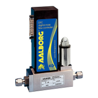
1 DPC Mass Flow Controller shown with an upstream valve confi guration
4
2 DPC Mass Flow Controller shown with a downtream valve confi guration 4
3 DPC 8-pin Mini-DIN Connector Confi guration 6
4 DPC RS-232 Communication Interface Connections 10
5 DPC RS-485 Communication Interface Connections 11
6 DPC First Banner Screen 18
7 DPC Firmware and Communication Interface Information Screen 18
8 DPC Initial Process Information 18
9 Joystick 19
10 DPC Process Information Screens 21
11 Program Protection Screen 22
12 Program Protection Password Screen 22
13 Change PP Password Screen 23
14 PP Password Change Confi rmation Screen 24
15 General Settings and Valve Parameters Menus 24
16 Set Point Source Menu Selections 24
17 Changing Local Set Point value 25
18 Valve Mode Menu Selections 25
19 DPC Upper Levels Menu Structures 32
20 Selecting Gas Group 33
21 Add Mixture Menu Selection 39
22 Assigning a Name to the Mixture 40
23 Add Gas Component and Ratio 40
24 Selecting Gas Component 40
25 G1 Component with Selected Gas 41
26 G1 Component with Highlighted Ratio Values 41
27 Mixture with 4 Components Ready to be Saved 42
28 Mixture Saved Confi rmation Message 42
29 “User-Defi ned Mixture” Menu Selection with new MyMix1 Mixture 43
30 "Edit Mixture" Menu Selection 43
31 Reset Totalizer Screen 50
32 Totalizer Reset Confi rmation 50
APPENDIX IV: INDEX OF FIGURES
APPENDIX IV: INDEX OF FIGURES