5
CAUTION: To avoid obstructions and contamination in the sensor tube and the
narrow fl ow channels in the laminar fl ow element, the user should install the
instrument in process lines that have clean gases. Upstream particulate
fi lters with maximum particulate size 20µ are recommended for all
applications.
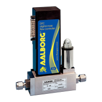
2.4 Mounting
DPC04/07/14/17/37/47/57/66/77 series Mass Flow Controllers have mounting holes with
6-32 thread (8-32 thread for DPC 57/67/77) on the bottom of the instrument body for
mounting to fl at panels. See APPENDIX II for exact dimensions.
The DPC Mass Flow Controller can be mounted in any position. It is not required to maintain
straight runs of pipe upstream or downstream of the instrument. It is preferable to install
the controller in a stable environment, free of frequent and sudden temperature changes,
high moisture, and drafts.
DPC controller ports are equipped with 10-32 female thread (DPC04/07), 1/8" NPT female
thread (DPC14/17/37), 1/4" NPT female thread (DPC47), 1/2" NPT female thread (DPC57)
and 3/4" NPT female thread (DPC67/77).
3. Electrical Connections
DPC instrument is equipped with an 8 pin-MiniDIN power, analog/relay output, interface con-
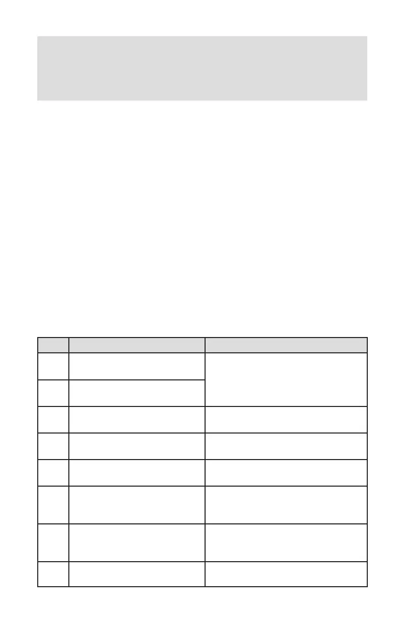
nector. Table I explains the pin designations. See Figure 3 for a Pin Diagram.
PIN FUNCTION NOTE
1
Solid State SPST Relay NO
(normally open) contact #1
Do not exceed SSR
maximum voltage 48 AC peak/DC and
maximum load current 400 mA.
2
Solid State SPST Relay NO
(normally open) contact #2
3
Analog Set Point Input (+)
(0-5Vdc, 0-10Vdc, 4-20mA)
Input Impedance: 100K (0-5, 0-10 Vdc)
250 Ohm (4-20 mA)
4
Analog (0-5Vdc,0-10Vdc,4-20 mA)
Input/Output reference (-)
Common (return) for pins 3 and 6 (0-5Vdc
or 0-10 Vdc or 4-20 mA)
5 Not Assigned. Do Not Connect!
Factory use only. Do Not Connect any
signals to this pin!
6
Analog (0-5Vdc, 0-10Vdc or 4-20
mA) Output (+)
Output. Do not apply external voltage or
any current source. Be sure to observe
recommended load impedance.
7 Power supply, positive (+)
Power input 12 – 26 Vdc.
(DPC04/07/14/17/37/47) or 24-26Vdc
(DPC57/67/77).
8 Power supply, common (-) Power input common.
TABLE I: 8-PIN DESIGNATIONS AND NOTES