18
6. OPERATING INSTRUCTIONS
6.1 Preperation and Power Up
Initially, after the power is fi rst turned on, the Banner Screen is shown for 2 seconds (see
Figure 6), then device fi rmware and EEPROM database revisions will be displayed on the
fi rst line, communication interface type and hexadecimal address value on the second line,
Communication Port baud rate on the third line, and Modbus hardware status and decimal
address value on the fourth line (see Figure 5). These are shown for another 2 seconds.
Subsequently, the actual process information (PI) is displayed.
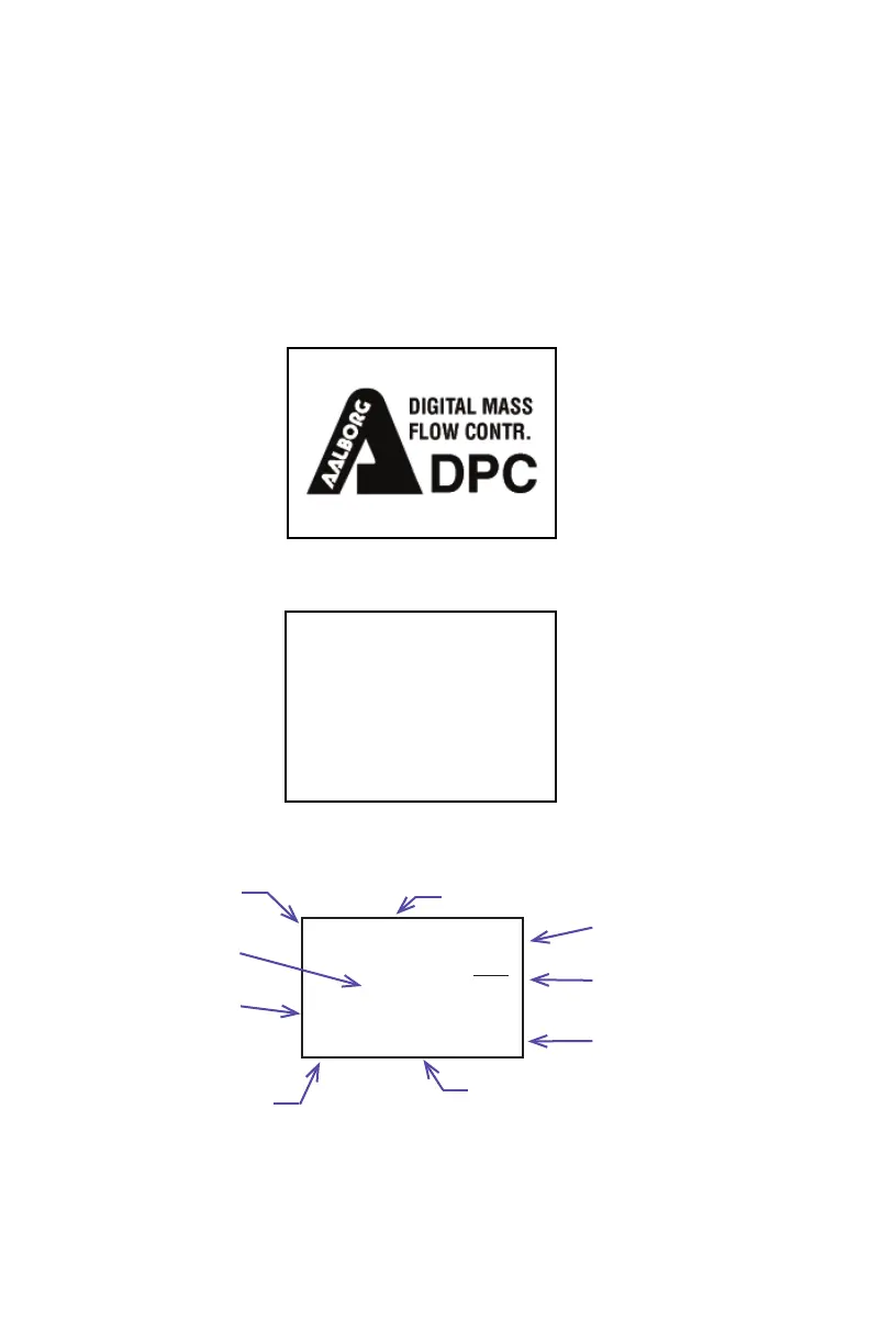
Figure 6: DPC fi rst Banner Screen
Figure 7: DPC Firmware and Communication Interface Informain Screen
Fw: A001 Tbl: A001
COM:RS232 Add: 11
Baud Rate: 9600
ModBus: Y Add: 11
PSIA
14.67
27.7
Sml
min
SD:
0.0 Sml/min
0.0
Temperature Reading
Current Unit of
Measure for Mass Flow
Absolute Pressing
Reading
Current Mass Flow
Rate Reading
Current Valve Mode:
Current Set Point
Units of Measure
C - Closed
A - Auto
O - Opened
A
Current Set Point Source:
A - Analog
L - Local
D - Digital Interface
P - Program Set Point Table
Absolute Pressure Units of Measure
Current Set Point Value
Figure 8: DPC INITIAL PROCESS INFORMATION SCREEN