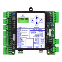
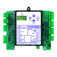
31MHGRVX-A2 Module Technical Guide
APPENDIX C: REHEAT EXPANSION MODULE
Operation Modes
Initialization
The Reheat Expansion Module uses on-board LEDs to indicate
various diagnostic conditions during power-up and operation. See
the LED Operation section on page 32 for more information.
Modulating Hot Gas Valves
Each Reheat Expansion Module utilizes two modulating valves
to control the ow of Hot Gas through the Hot Gas Reheat Coil.
One of these valves is the Condenser Hot Gas Valve and the other
is the Hot Gas Reheat Valve. The valves are wired to the Reheat
Expansion Module’s Modulating Hot Gas Valve Output terminals.
These valves work in concert with each other to create a “three-way
valve” conguration. As one closes, the other opens, etc. All modes
of operation that follow referring to the Hot Gas Reheat Valve are
actually a combination of these two valves working together to
achieve the specied sequence of operation.
Mode of Operation
The Reheat Expansion Module(s) can be used in MHGRVX-A2
Stand-Alone Mode and when the MHGRVX-A2 is communicating
to an AAON unit controller.
Stand-Alone Mode
See page 11 for MHGRVX-A2 Stand-Alone Mode. Once the Reheat
Expansion Module’s Binary Input Compressor input is enabled, the
valve positions follow the MHGRVX-A2.
Operation in Communicating Mode
In this mode, the MHGRVX-A2 behaves as an expansion board for
an AAON unit controller. See page 12 for detailed operation. Once
the Reheat Expansion Module’s Binary Input Compressor input is
enabled, the valve positions follow the MHGRVX-A2.
Additional Features
Reheat Coil Flush
To assure positive oil return to the compressor, the Hot Gas Reheat
Coil will be ushed of liquid refrigerant by moving the Modulating
Gas Reheat Valve to its maximum position for a short interval.
Cooling Flush
If the unit is in cooling mode, a ush will occur when the unit’s
ush cooling interval timer has elapsed. The time is accumulated
whenever it is in cooling mode and resets after each ush cycle.
The ush cooling interval timer is a setpoint that is congurable
using the keypad and display (0 to 120 minutes in 10 minute
increments). If enabled, each Reheat Expansion Module follows
the same sequence as the MHGRVX-A2, using the same cooling
ush interval timer of the MHGRVX-A2. The expansion boards do
not ush at the same time.
Reheat Mode Flush
If the unit is in dehumidication mode and the valve is below 70%
for the ush reheat interval timer value, a ush will occur. If the
valve goes above 70%, the timer is reset. The ush reheat interval
timer is a setpoint that is congurable using the keypad and display
(0 to 120 minutes in 10 minute increments). If enabled, each Reheat
Expansion Module follows the same sequence as the MHGRVX-A2,
using the same ush reheat interval timer of the MHGRVX-A2. The
expansion boards do not ush at the same time.
Optional Flush Mode Congurations
A conguration option is available that will provide a 30 second
ush cycle whenever the unit enters the cooling, dehumidication,
and heat pump modes. If using Reheat Expansion Module(s) in
conjunction with the MHGRVX-A2, a conguration option is
available to force all the valves to ush synchronously instead of
independently.
Contact AAON Controls Support for assistance in making these
conguration changes.