32MHGRVX-A2 Module Technical Guide
APPENDIX C: REHEAT EXPANSION MODULE
LED Diagnostics and Troubleshooting
LED Diagnostics
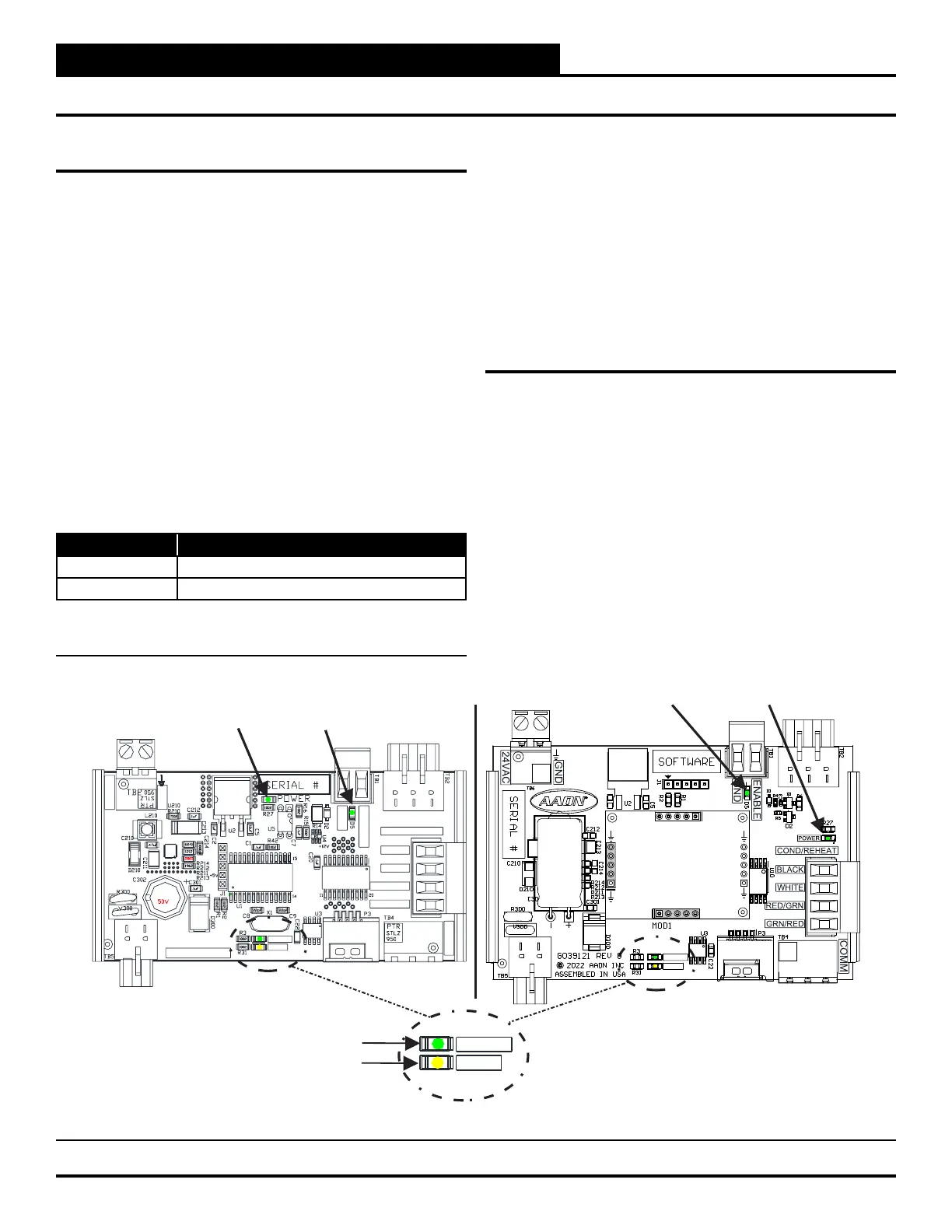
The Reheat Expansion Module is equipped with four LEDs that can
be used to verify operation and perform troubleshooting.
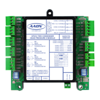
See Figure 10, this page for the LED locations. The LEDs
associated with these inputs and outputs allow you to see what is
active without using a voltmeter. The LEDs and their uses are as
follows:
Operation LEDs
• POWER: This green LED will light up to indicate that 24
VAC power has been applied to the Expansion Module.
• STATUS: This green LED will light up and blink every
10 seconds according to valve position. One blink per
10%. Example: valve position is 67%. STATUS LED will
blink six times every 10 second cycle. The STATUS LED
will stay on solid during the two-minute ush cycle. See
Table 9, this page.
Communication LED
• COMM: This amber LED will light up and blink once
for every good packet received. Packets should be sent
once every second, so the COMM LED should blink the
same, once every second. The COMM LED should blink
simultaneously on all modules.
Binary Input LED
• COMPRESSOR ENABLE: This green LED will light up
when the Reheat is enabled.
LED Troubleshooting
• “POWER” LED: When the Reheat Expansion Module is
powered up, the POWER LED should light up and stay on
continuously. If it does not light up, check to be sure that
the power wiring is connected to the board, the connections
are tight, and the transformer is powered. If after making
all these checks, the POWER LED does not light up, the
board is probably defective.
• “STAT” LED: When the board is rst powered up, the
STAT LED will do the following:
○ On for 10 seconds
○ Blinks 30 times
○ Status code repeatedly blinks the indicated valve position
every ten seconds
No. of Blinks STATUS LED
1-10 Per 10% valve position
Solid During two-minute ush cycle
Table 10: Reheat Expansion Module ALARM LED
Blink Codes
24VAC
GND
COMM
GND
ENABLE
BLAC
K
WHITE
RED/GR
N
GRN/RED
COND/REHEAT
YS102608 R0
COMM
STATUS
COMM LED
STATUS LED
COMM
STATUS
COMPRESSOR ENABLE LED
POWER LED
4750
1785
.1uF
4750
COMM
STATUS
PTR
STLZ
950
PTR
STLZ
950
1000uF 50V 1000uF 50V
POWER LED
COMPRESSOR ENABLE LED
Figure 9: Reheat Expansion LED Locations and Descriptions