VCC-X Operator Interface SD
VCC-X CONFIGURATION
31
VCC-X Confi guration Screens
period. By the time the difference is 1˚, the signal change will be
2% per time period. With a Proportional Window of 2˚, if you are 2˚
or more from setpoint, the amount of signal change will be 10% per
time period, and at 1˚ from setpoint the change would be 5% per time
period. So, a larger proportional window allows for fi ner tuning of
the control signal to prevent overshooting. Default is 10.0ºF/5.55ºC.
Description Minimum Default Maximum
Economizer Control
Rate
1 sec 10 sec 30 sec
Proportional Window 1.0ºF
0.10ºC
10.0ºF
5.55ºC
30.0ºF
16.6ºC
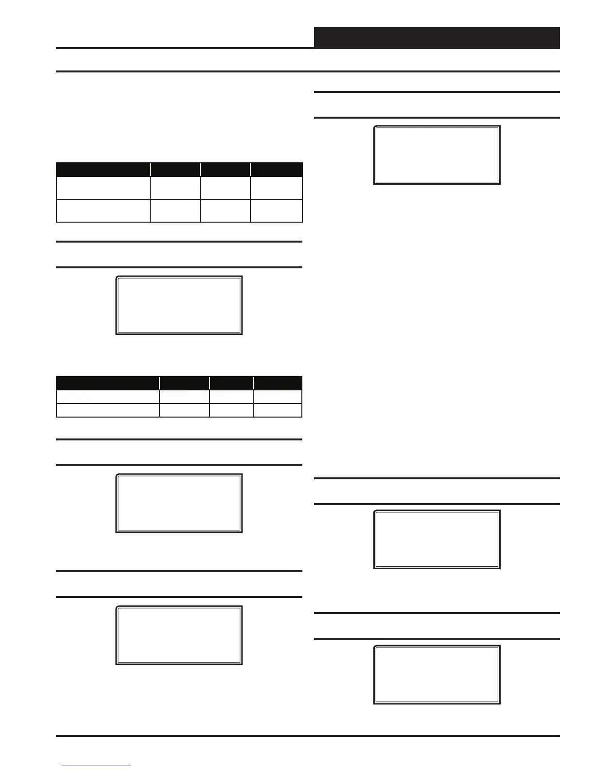
Confi guration Screen #34 - Economizer
Voltage Output
VCC-X Cnfg ID #
Econo Voltage Output
Min Volts: 2.0VDC
Max Volts: 10.0VDC
Enter a value between 0.0 and 10.0 VDC for the Economizer mini-
mum and maximum output voltage. Defaults are 2 VDC Min and
10 VDC Max.
Description Minimum Default Maximum
Min Economizer Voltage 0 2 10
Max Economizer Voltage 0 10 10
Confi guration Screen #35 - CO
2
Sensor
Installed
VCC-X Cnfg ID #
CO2 Sensor Installed
NO
USE < or > TO CHANGE
Select YES if you have a CO
2
Sensor installed. Default is NO.
Confi guration Screen #36 - Building Pressure
Sensor Installed
VCC-X Cnfg ID #
Building Pr. Sensor
Installed
None
If this unit has a Building Pressure Sensor installed, select Analog if
it is a wired sensor. Select Receive Broadcast if the Building Pres-
sure Sensor is attached to a separate device that will broadcast the
reading, e.g., GPC-XP Controller. Default is None.
Confi guration Screen #37 - Building Pressure
Control
VCC-X Cnfg ID #
Building Pr. Control
None
USE < or > TO CHANGE
Default is None. Available options are:
None—No Building Pressure Control by this controller.
On/Off Exh Relay—If an On/Off Exhaust Fan is being
used, select this option and confi gure a relay output as
Exhaust Fan. If the building pressure rises above
setpoint, this relay will energize. This is Direct-Acting
control.
Modulating Exh—If the building pressure rises above
setpoint, a modulating signal will be used to control an
exhaust fan VFD or a modulating damper to maintain
setpoint. A relay confi gured as Exhaust Fan can be used
to enable this device so that the modulating signal can
control it. This is Direct Acting control.
OA Damper—Select if reverse acting Building Pressure
Control using the Outdoor Air Damper is required. If
the building pressure falls below setpoint, the OA
Damper (Economizer) signal will be used to modulate
the OA Damper to maintain setpoint. This is Reverse
Acting control.
Supply Fan—Contact WattMaster Factory regarding
this reverse acting Building Control option. This should
not be used in most applications. This is Reverse Acting
control.
Confi guration Screen #38 - Building Pressure
Control Rate
VCC-X Cnfg ID #
Building Pr. Control
Rate: 10 Sec
[ 1 - 30 Seconds ]
Default is 10 seconds. The Building Pressure Control Rate is the
time period between changes to the Building Pressure Control signal.
Confi guration Screen #39 - Building Pressure
Control Max Adjust
VCC-X Cnfg ID #
Building Pr. Control
Max Adjust: 5%
[ 1 - 30% ]
This is the maximum amount that the Building Pressure Control
output can adjust to when it needs to. Default is 5 percent.
 Loading...


