VAV/ZONE CONFIGURATION
VCC-X Operator Interface SD
72
VAV/Zone Confi guration Screens
VAV/Zone Confi guration
In order to correctly set up the VAV/Zone Controller, you must fi rst
confi gure several parameters in regard to the type of system and
operating parameters for the VAV/Zone Controller you have installed.
Most of these values and operating parameters are only set once at
the initial system setup and are never changed.
Modular Service Tool Instructions
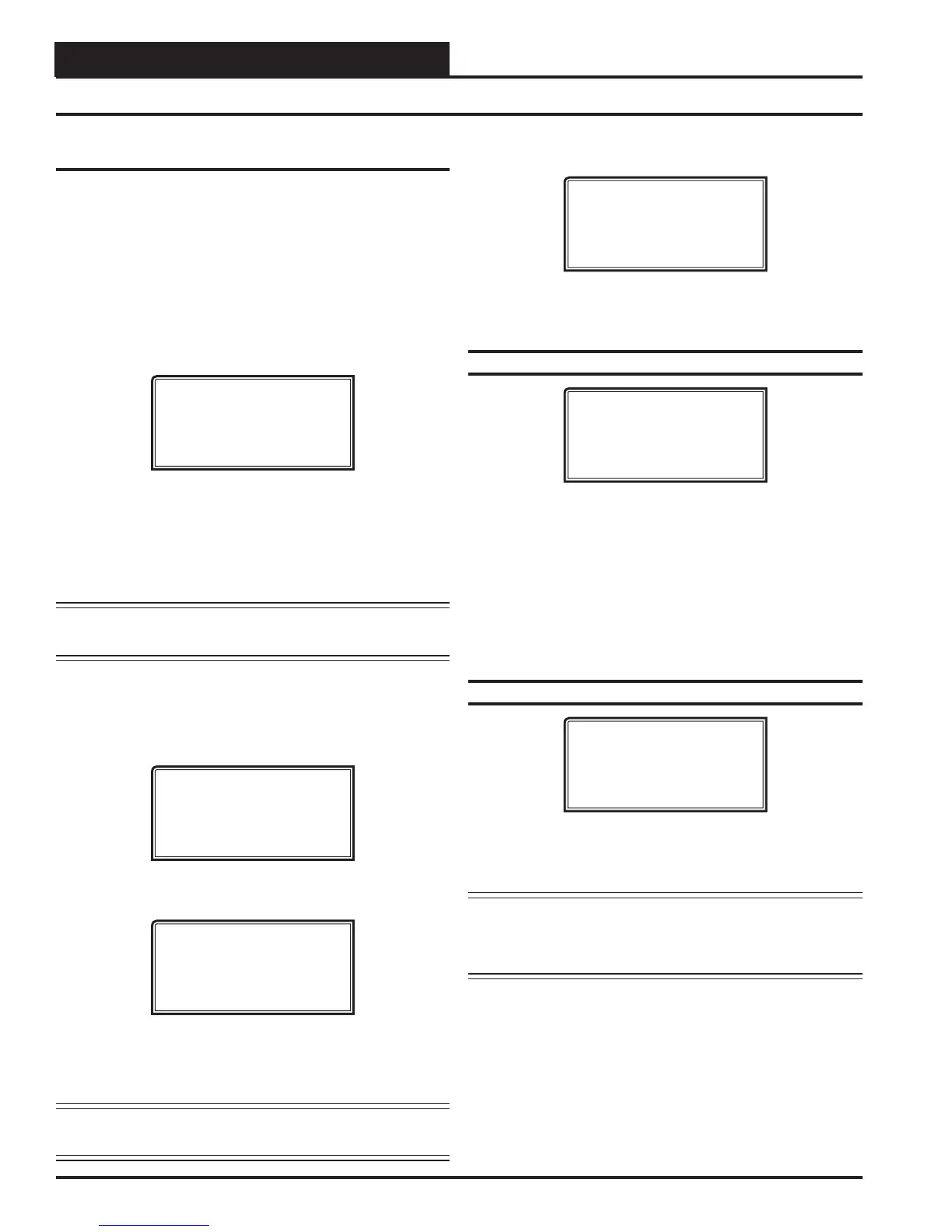
From any Menu Screen, press the <CONFIGURATION> button. The
Unit Selection Screen, shown below, will appear requesting that you
enter the unit ID number.
Enter Unit Address
Then Press Enter
Selected Unit#: XXXX
No Communication
Enter the correct unit ID number of the VAV/Zone controller you
want to confi gure, and press <ENTER>. Once communication is
established, “No Communication” will be replaced with “Press
Down.” Then
press <>. You will then see Unit Confi guration Screen
#1
. Press <ENTER> to save entered data and press <> to scroll
through the screens.
NOTE: If “No Communication” remains, it indicates a
communication failure to the controller.
System Manager SD Instructions
From any Main screen, press <SETPOINTS>. The screen below
will appear because this option requires passcode clearance. Only a
Level 2 passcode can change setpoints.
THIS ACTION REQUIRES
PASSCODE CLEARANCE
Enter Passcode: XXXX
If the correct passcode was entered, the Unit Selection Screen will
be displayed.
Enter Unit Address
Then Press Enter
Selected Unit#: XXXX
No Communication
Enter the Unit ID of the controller you want to confi gure and press
<ENTER>. Once communication is established, “No Communica-
tion” will be replaced with “Press Down.”
NOTE: If “No Communication” remains, it indicates a
communication failure to the controller.
The following screen will be displayed:
Change Setpoints
Configure Unit
Save/Copy/Restore
Scroll down to the ‘Confi gure Unit’ option and press <ENTER>.
This will take you to the fi rst Confi guration Screen shown below.
Confi guration Screen #1 - Box Confi guration
XX Box Cnfg IDXXXX
Box Configuration
COOLING ONLY BOX
Use < Or > To Change
This Box Control Code will operate in one of four possible modes.
The box designation will display on the top line of all screens.
0 = COOLING ONLY BOX (will display as CO Box)
1 = H/C CHANGEOVER BOX (will display as HC Box)
2 = SERIES FAN BOX (will display as SF Box)
3 = PARALLEL FAN BOX (will display as PF Box)
Confi guration Screen #2 - Damper Operation
XX Box Cnfg IDXXXX
Damper Operating
Mode: DIRECT ACTING
Use < Or > To Change
Select Direct Acting or Reverse Acting. If the damper opens in a
clockwise direction, it is DIRECT ACTING. If the damper opens in
a counter-clockwise direction, it is REVERSE ACTING.
CAUTION: If you change this setting, you MUST cycle
power to the controller to allow it to re-calibrate
the damper feedback positions for its new
direction of control!