1. Additional clearance may be required
to allow for coil removal. See Table 3
2. May be installed flush depending
upon local codes.
3. For units with internal control panel,
the clearance in the table is needed for
either front or back, but not both. The
clearance is for supply fan removal.
If no internal control panel, front or
back clearance is 15.2 centimeters (6
inches) with note #2.
Table 3 – Coil Removal Clearances
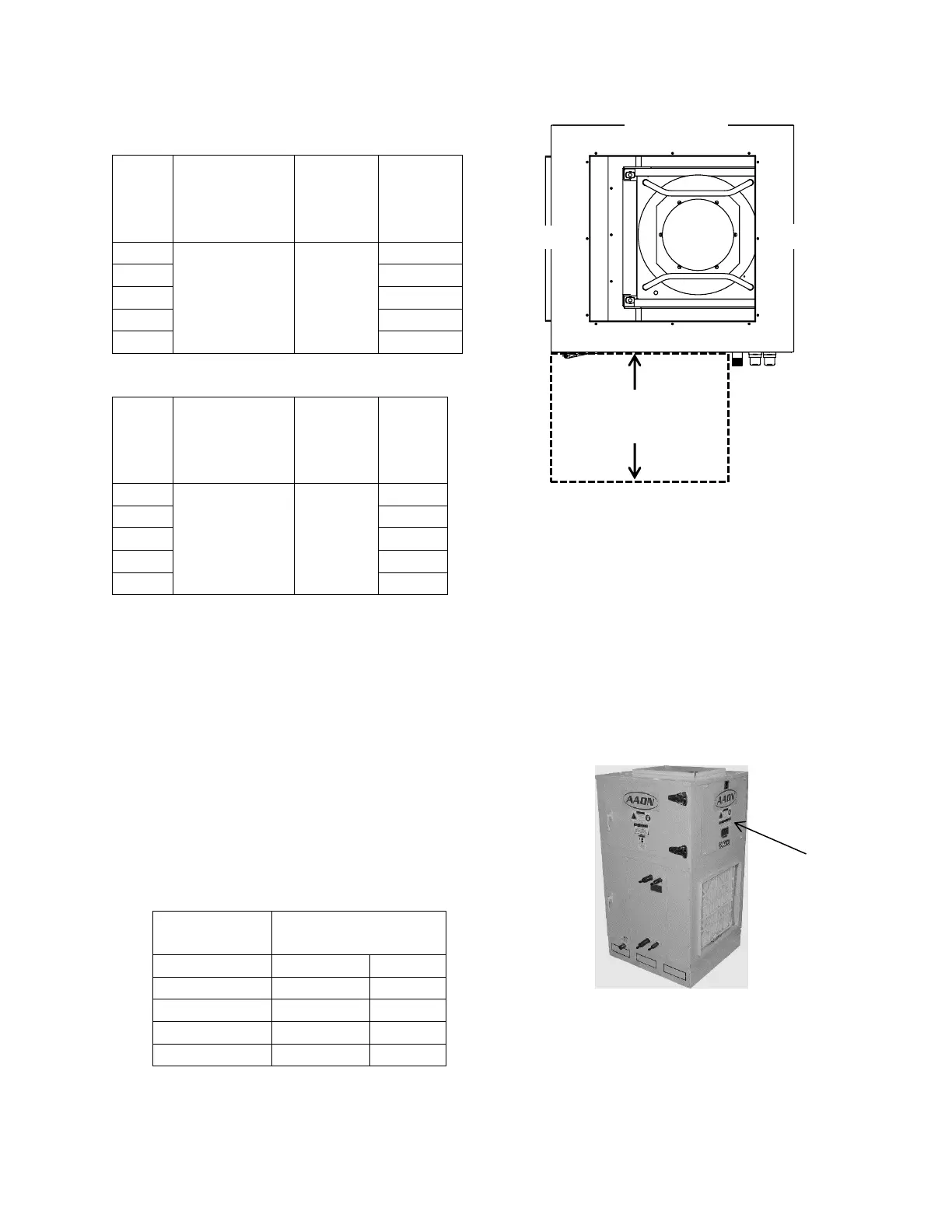
Figure 2 - Minimum Clearance Required for
Access to Unit (V3 Series plan view)
Internal Control Panel
V3 units with internal control panel have
removable access panels on the front and
back of the supply fan section. V3 units that
have energy recovery only have one
removable access panel on the front of the
unit. The supply flanges can be interchanged
with the access panels if necessary as the
openings have the same dimensions.
Figure 3 - V3 internal control panel with
rear removable access panel shown



 To Next Page