37
If power to the unit must be off for more than
an hour, turn the thermostat system switch to
"OFF", or turn the unit off at the control
panel, and leave the unit off until the main
power switch has been turned on again for at
least 24 hours for units with compressor
crankcase heaters. This will give the
crankcase heater time to clear any liquid
accumulation out of the compressor before it
is started.
Always control the unit from the thermostat,
or control panel, never at the main power
supply, except for emergency or complete
shutdown of the unit.
During the cooling season, if the air flow is
reduced due to dirty air filters or any other
reason, the cooling coils can get too cold
which will cause excessive liquid to return to
the compressor. As the liquid concentration
builds up, oil is washed out of the
compressor, leaving it starved for lubrication.
The compressor life will be seriously
shortened by reduced lubrication and the
pumping of excessive amounts of liquid oil
and refrigerant.
Note: Low Ambient Operation
Air-cooled DX units without a low ambient
option, such as condenser fan cycling or the -
17.8°C (0°F) low ambient option, will not
operate in the cooling mode of operation
properly when the outdoor temperature is
below 12.8°C (55°F). Low ambient and/or
economizer options are recommended if
cooling operation below 12.8°C (55°F) is
expected.
Evaporator Coil
The air handling unit coils are pressurized.
The copper caps must be punctured to permit
a gradual escape of the pressure prior to
un-sweating those caps. Immediately couple
the tubing to the indoor unit to avoid
exposing the coils to moisture. A properly
sized filter drier is furnished in the condenser.
When making solder connections, make sure
dry nitrogen flows through the lines, when
heating the copper, to prevent oxidization
inside of the copper. Field piping between
the condensing unit and the air handler is
required. Line sizes must be selected to
meet actual installation conditions, not
simply based on the connection sizes.
Thermal Expansion Valve
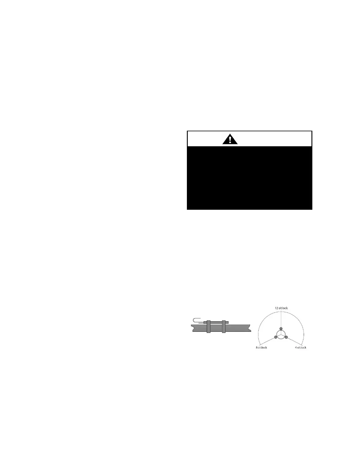
Thermal expansion valve bulbs must be
mounted with good thermal contact on a
horizontal section of the suction line close to
the evaporator, but outside the cabinet, and
well insulated. On suction lines less than or
equal to 22 mm (7/8”) OD, mount in the 12
o’clock position. On suction lines greater
than 2 mm (7/8”) OD, mount in either the 4
o’clock or 8 o’clock position.
Figure 23 - TXV Bulb Position
Hot Gas Reheat
Hot Gas Reheat (HGRH) is available for use
with DX systems that need humidity control.
The AAON modulating hot gas reheat system
diverts hot discharge gas from the condenser



 To Next Page