24
Control Box
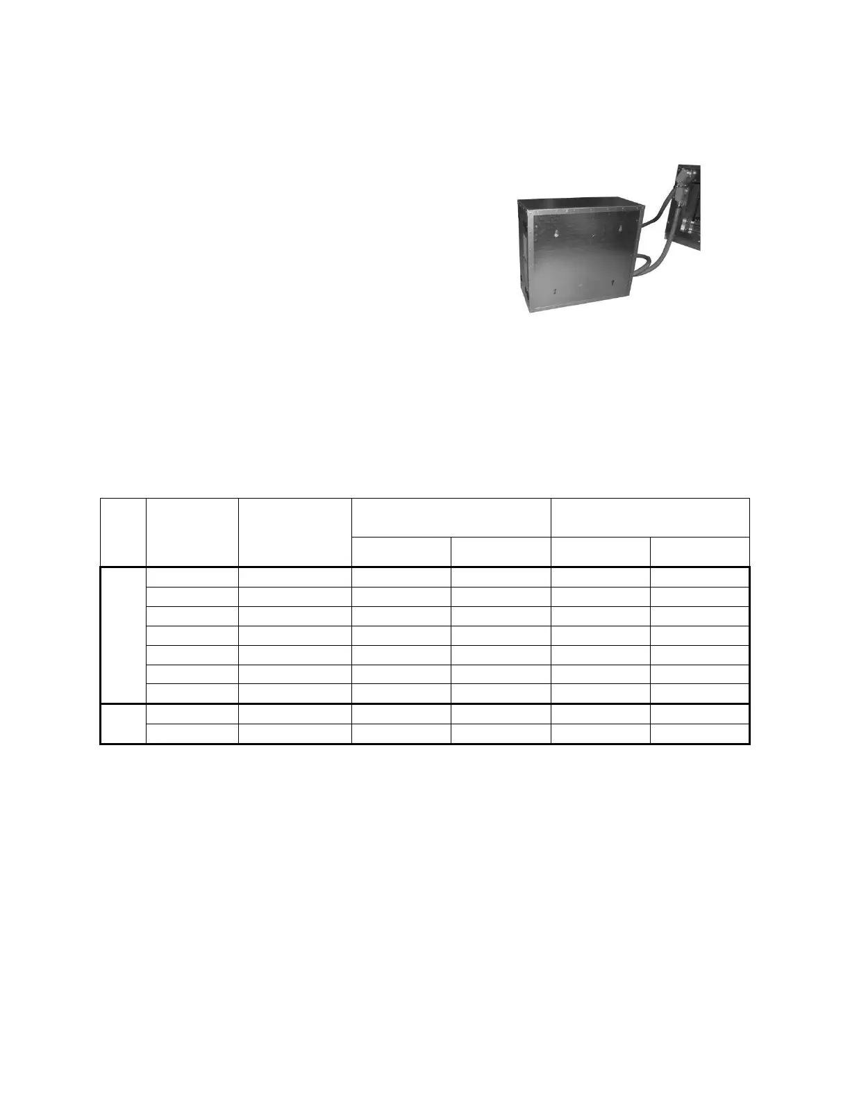
Some V3 units include an external control
box that must be mounted in the field. The
control box is designed with two mounting
holes on the back panel. Make sure the wall
fasteners can hold the weight of the control
box. See Figure 14.
External control boxes provided with
conduit exceeding 1.8 m (6ft) in length must
have conduit supported in compliance with
the National Electrical Code NFPA 70.
FMC and LMFC conduit must be supported
within 30.5 cm (12 in.) of both the unit and
the external control box and at intervals no
more than 1.4 m (4.5 ft) along the length.
Figure 14 - Back View External Control
Box
Electrical
Verify the unit nameplate agrees with power supply. Connect power and control field wiring as
shown on the unit specific wiring diagram provided laminated and attached to the door in the
controls compartment.
Table 4 - Nameplate Voltage Markings & Tolerances
Notes:
1. Operating voltage is the min and max voltage for which the unit can function. Never
operate outside of this min and max voltage.
2. The Acceptable Performance Range is the min and max voltage for which the unit
performance is designed and rated to give acceptable performance.



 To Next Page