38
to the air handling unit through the hot gas
line. Field piping between the condensing
unit and the air handler is required. Line
sizes must be selected to meet actual
installation conditions, not simply based
on the connection sizes.
The line delivers the hot discharge gas to the
reheat coil and/or the hot gas bypass valve, so
it is sized as a discharge line.
Hot Gas Bypass
Hot Gas Bypass is available for use with DX
systems that may experience low suction
pressure during the operating cycle. This may
be due to varying load conditions associated
with VAV applications or units supplying a
large percentage of outside air. Hot Gas
Bypass is not necessary in units with variable
capacity compressors. The system is
designed to divert refrigerant from the
compressor discharge to the low pressure
side of the system in order to keep the
evaporator from freezing and to maintain
adequate refrigerant velocity for oil return at
minimum load.
Hot discharge gas is redirected to the
evaporator inlet via an auxiliary side
connector (ASC) to false load the evaporator
when reduced suction pressure is sensed.
Field piping between the condensing unit
and the evaporator is required. Line sizes
must be selected to meet actual installation
conditions, not simply based on the
connection sizes.
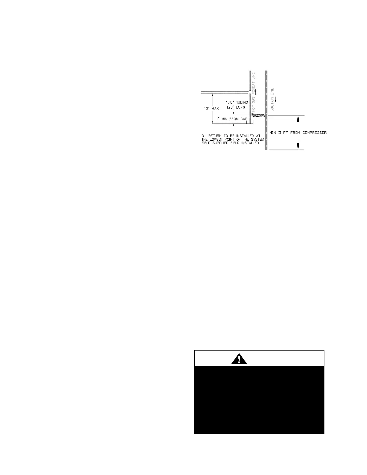
Purge Circuit
The purge circuit is required on hot gas reheat
or hot gas bypass lines. The purge circuit
needs to be field furnished and installed at the
lowest point of the line set.
With this installation, oil drains into the drain
leg of the hot gas reheat line. Oil accumulates
until it reaches the level of the 3 mm (1/8”)
capillary tubing.
The combination of capillary action and the
pressure difference between the hot gas
reheat line (high pressure) and the suction
line (low pressure) causes the oil to travel
through the capillary tube into the suction
line of the first circuit to return the oil to the
compressor. The capillary tube connection to
the suction line of the first circuit must be a
minimum of 1.5 meters (5 feet) from the inlet
to the compressor to allow the oil time to
dissipate into the suction vapor and not slug
the compressor with liquid oil.
Adjusting Refrigerant Charge
Adjusting the charge of a system in the field
must be based on determination of liquid sub-
cooling and evaporator superheat. On a
system with a TXV, liquid sub-cooling is
more representative of the charge than
evaporator superheat but both measurements
must be taken.



 To Next Page