23
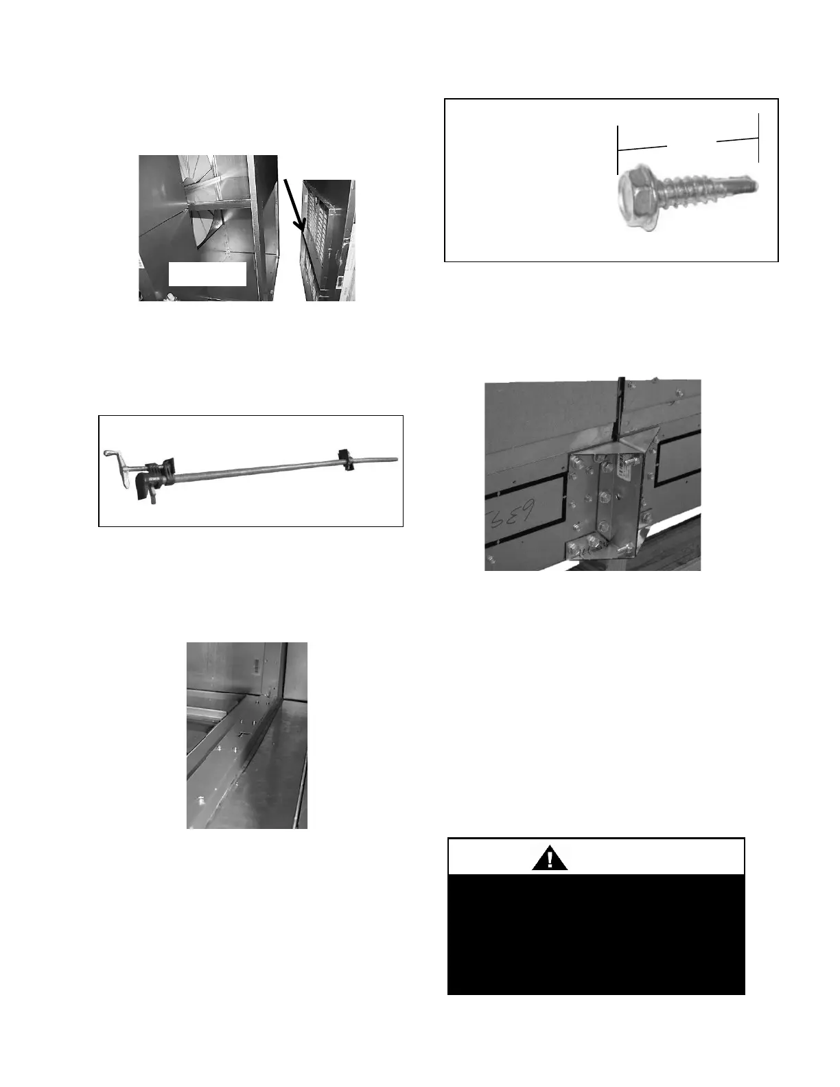
Push section 1 and 2 together so that the
flange from section 1 is inside of section 2.
Figure 9 - Connect Sections
Use bar clamps or other non-destructive
winching device to pull the tops of the
modules together tightly.
Figure 10 - Bar Clamp
At each of the pre-drilled holes in the flange,
drill 8 mm (5/16”) head self-tapping screws
to secure the two sections together.
Figure 11 - Flange Overlap
Figure 12 - Self-Tapping Screw
V3 units with a forklift base must be bolted
together at the connecting sections. See
Figure 13
Figure 13 - Forklift Base Assembly
4. Re-attach Access Side Panels
5. Final Sealing
It is very important to keep air from
infiltrating the unit cabinet. Seal all piping
penetrations with Armaflex, Permagum or
other suitable sealant. Also seal around drain
connections, electrical connections and all
other inlets where air may enter the cabinet.
This is especially important when the unit is
installed in an unconditioned area.
Proper sealing of the electrical and
piping entries into the unit must be
verified. Failure to seal the entries
may result in damage to the unit and
property.



 To Next Page