47
Energy Recovery Units
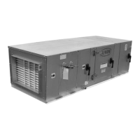
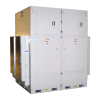
Some V3 units have been equipped with an
energy recovery wheel. AAON provides
options for either an aluminum energy
recovery wheel or a polymer energy recovery
wheel. Follow the instructions for the
specific type of energy recovery wheel in
your installed equipment.
The Energy Recovery Cassette consists of a
frame wheel, wheel drive system, and energy
transfer segments. Segments are removable
for cleaning or replacement. The segments
rotate through counter flowing exhaust and
outdoor air supply streams where they
transfer heat and/or water vapor from the
warm, moist air stream to the cooler and/or
drier air stream.
The initial setup and servicing of the energy
recovery wheel is very important to maintain
proper operation efficiency and building
occupant comfort.
Normal maintenance requires periodic
inspection of filters, the cassette wheel, drive
belts, air seals, wheel drive motor, and its
electrical connections.
Wiring diagrams are provided with each
motor. When wired according to wiring
diagram, energy recovery wheel rotates
clockwise when viewed from the shaft/pulley
side.
By carefully reviewing the information
within this section and following the
instructions, the risk of improper operation
and/or component damage will be
minimized.
It is important that periodic maintenance be
performed to help assure trouble free
operation.
Initial Mechanical Check and Setup
Outdoor air intake adjustments must be made
according to building ventilation, or local
code requirements.
After the unit installation is complete, open
the cassette access door and determine that
the energy wheel rotates freely when turned
by hand. Apply power and observe that the
wheel rotates at approximately 30 RPM. If
the wheel does not rotate when power is
applied, it may be necessary to readjust the
“diameter air seals”.
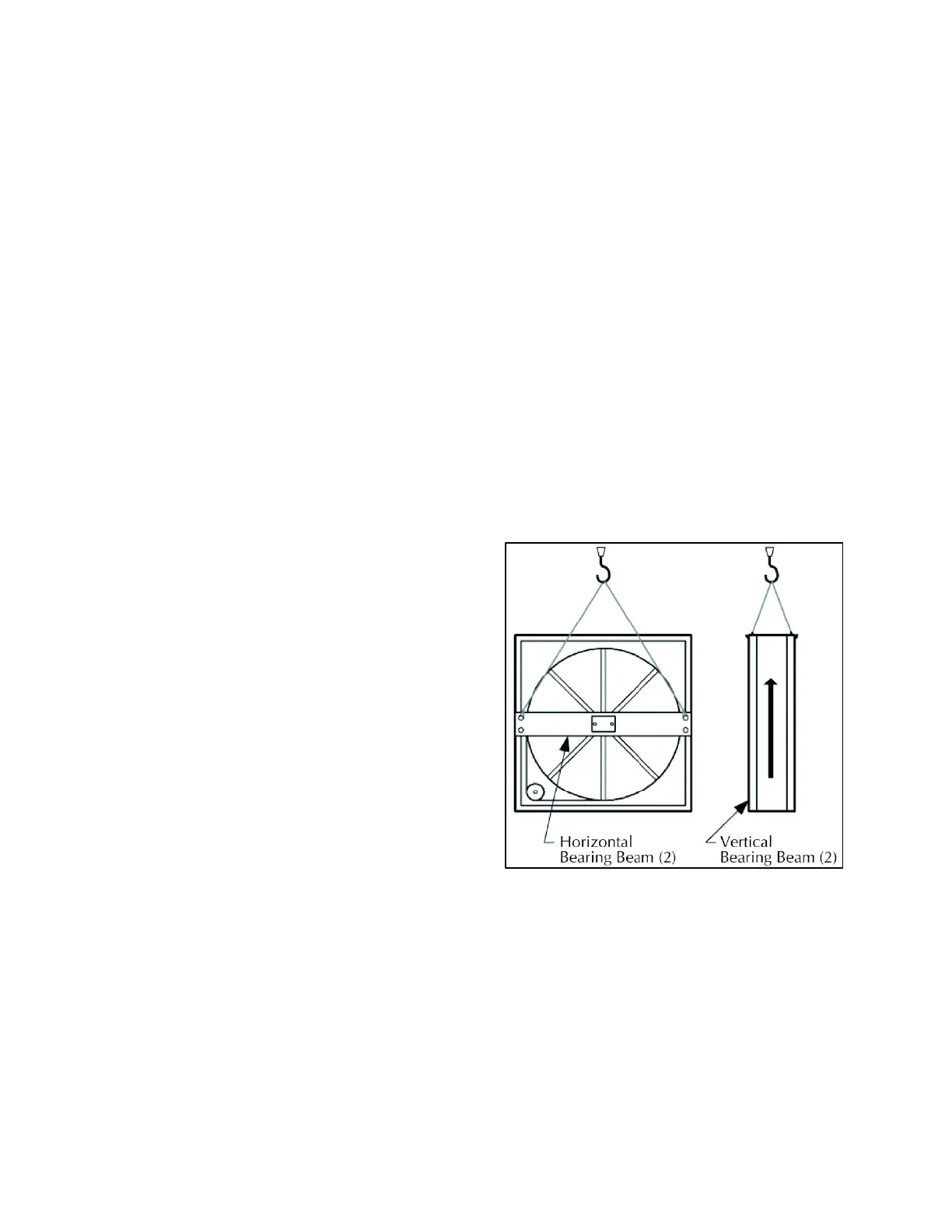
Handle cassettes with care. Lift all cassettes
by the bearing support beam. Holes are
provided on both sides of the bearing support
beams to facilitate rigging as shown in the
following illustration.
Figure 25 – Lifting Hole Locations
Airflow Balancing and Checking
High performance systems commonly have
complex air distribution and fan systems.
Unqualified personnel must not attempt to
adjust fan operation, or air circulation, as all
systems have unique operations
characteristics. Professional air balance
specialists must be employed to establish
actual operating conditions, and to configure



 To Next Page