22
Unit Assembly
Although V3 Series units are shipped factory
assembled as standard, the unit may be
ordered as shipping splits for certain
applications such as for assembly in existing
structures where modules must be
manipulated separately. If the unit was
ordered as shipping splits, then they must be
assembled in the field.
Locate the schematic in the equipment’s
literature packet.
1. Identify and Situate Splits
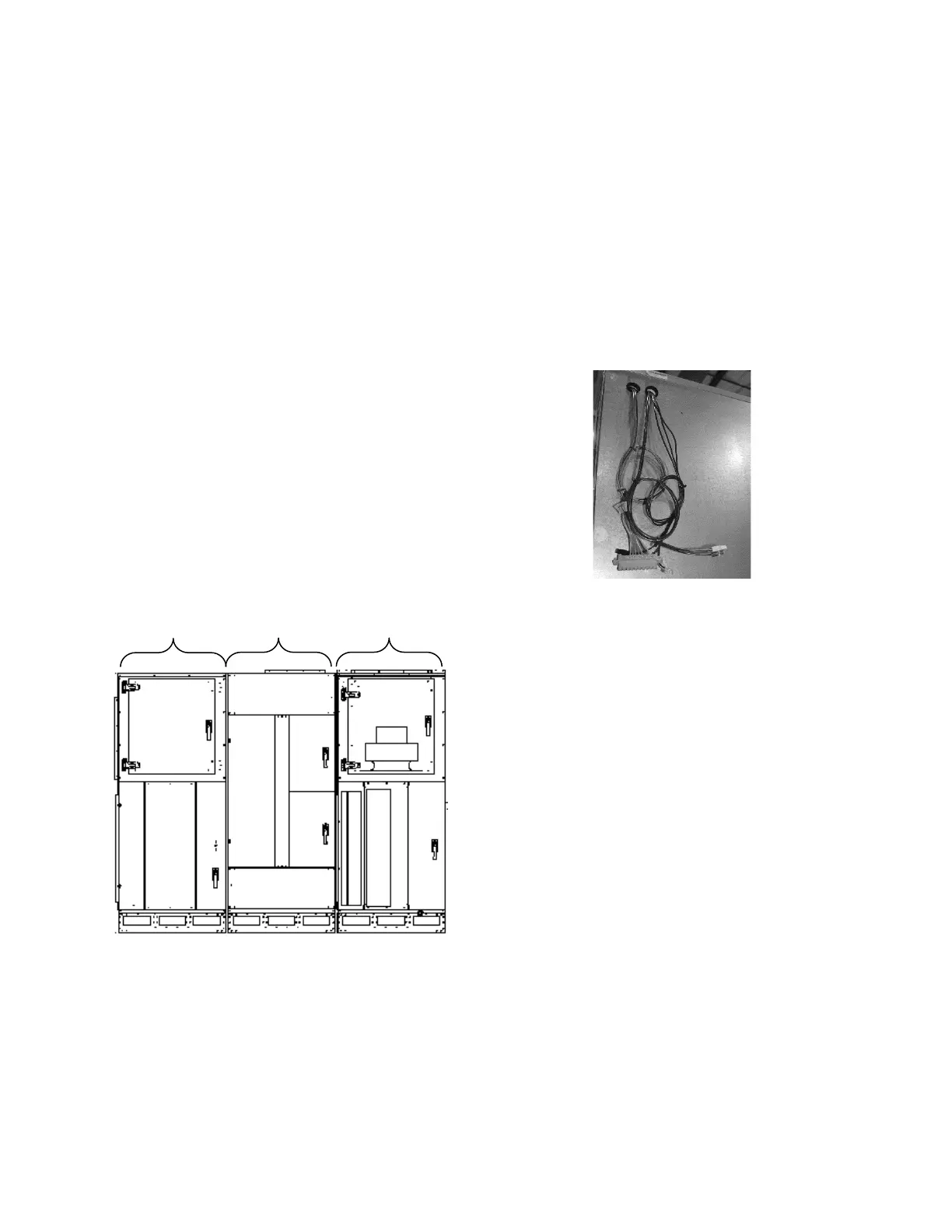
V3 Units can have the following ship split
sections:
1. Exhaust Fan
2. Energy Recovery
3. Air Handler
4. Pre Filter
5. Mixing Box
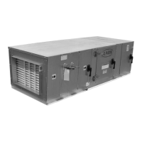
Figure 7 - V3 Schematic with (1) Exhaust
Fan, (2) Energy Recovery, (3) Air Handler
2. Connect Power and Control Wiring
between sections
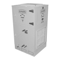
V3 Series units are equipped with low and
high voltage quick connects to connect
wiring from one section to the next. It might
be necessary to increase the hole size in the
cabinet in order to get the quick connector
through the opening. See the Electrical
section for more information.
Figure 8 - Low & High Voltage Quick
Connect
A color-coded wiring diagram is laminated
and affixed to the inside of the control
compartment access door.
V3 Series units are equipped with a single
point power connection. Wire from the unit
to external controls and power sources must
be provided in the field.
3. Connect Sections
Remove the access side panels by removing
the screws and pulling the panels off. Using
the V3 Schematic as an example, section 1
will have a duct flange, and it will connect to
section 2 on the side that does not have a
flange.
Apply 13 mm (½”) thick, 16 mm (5/8”) wide
adhesive gasket around the edges of the box
without the flanges.



 To Next Page