28
Fuses and Circuit Breakers
The interrupting rating of fuses and circuit
breakers is to be determined based on the
KAIC rating of the unit. Refer to the wiring
diagram for fuse sizing.
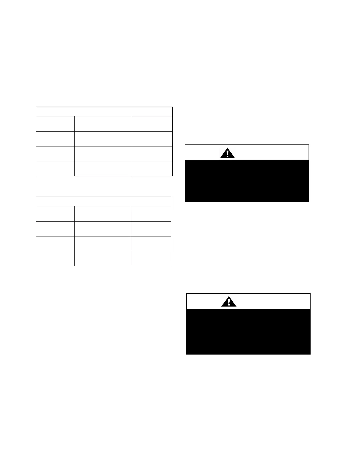
Table 6 – 35 KAIC Fuse Sizing
Table 7 – 65 KAIC Fuse Sizing
Duct Connection
Attach duct to flanges provided on the unit.
The installer is responsible for sealing ducts
to the flanges to prevent water leaks.
See Figure 6 for return and supply air duct
locations. Size ductwork in accordance with
the ASHRAE Handbook. Install ductwork in
accordance with NFPA Standard 90A.
When attaching duct to the unit, use a
flexible/compressible material rated for duct
connections. A 7.6 centimeter (3 inch)
flexible connector for both return and supply
duct connections is recommended.
Condensate Drain Pans
Units require field installed drain p-traps and
lines to be connected to the condensate drain
pans of the unit.
For condensate drain lines, the line must be
the same pipe size or larger than the drain
connection, include a p-trap, and pitch
downward toward drain. An air break must
be used with long runs of condensate lines.
See Installation section of this manual for
more information.
Condensate Drain Piping
A p-trap and drain line must be installed on
the drain connection, with the p-trap not to
exceed 15.3 cm (6”) from the drain
connection. The lines must be the same pipe
size or larger than the drain connection,
include a p-trap, and pitch downward toward
drain. An air break must be used with long
runs of condensate lines.
Draw-through cooling coils will have a
negative static pressure in the drain pan area.
This will cause an un-trapped drain to back
up due to air being pulled up through the
condensate drain piping.



 To Next Page