35
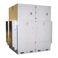
Figure 21 - Steam Distributing Piping
Table 10 - Steam Distributing Coil Sweat
Connection Sizes
Air handling units with steam heating coils
MUST BE installed high enough to allow for
a minimum of 0.3 meters (1 foot) condensate
drop leg off of the steam coil, or as
recommended by the steam trap
manufacturer. Lines must be insulated with
approved insulation and be properly fastened,
sloped, and supported according to local code
requirements.
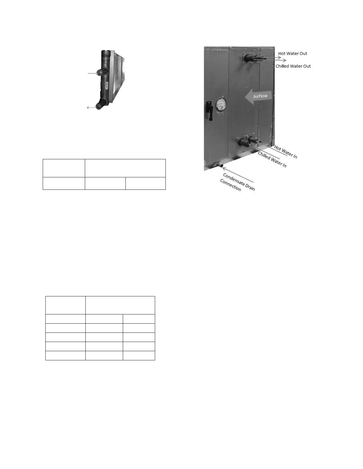
Table 11 - Hot Water Coil Sweat
Connection Sizes
Connect the hot water heating supply to the
bottom of the coil and return to the top.
Figure 22 - Hot & Chilled Water Piping
Water coils must not be subjected to entering
air temperatures below 3.3°C (38°F) to
prevent coil freeze-up. If air temperature
across the coil is going to be below this value,
use a glycol solution to match the coldest air
expected.
Water supply lines must be insulated,
properly fastened, drained, and supported
according to local code requirements.
Chilled Water Coil
Factory installed four, six or eight row chilled
water cooling coils can be factory mounted.
These coils are supplied from a building
chilled water source. All valve controls for
the cooling coil operation are field supplied
and field installed.
 Loading...