- 13 -
PHASE 4 - TRANSMITTER OPERATION
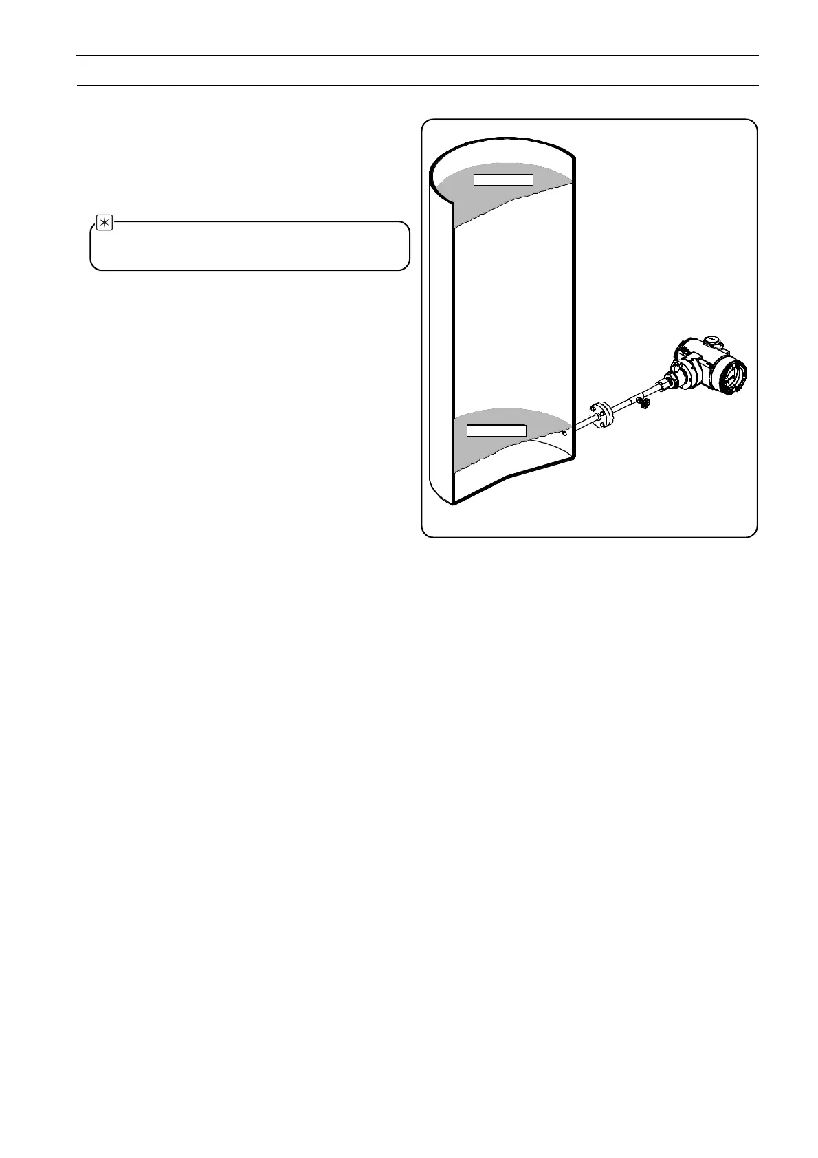
5.2 LEVEL MEASUREMENT
1. Vent all entrapped air from primary using vent/drain valves
on the transmitter, then close them.
2. Make sure to have the level in the tank at the required
reference (minimum) level
.
Note - In case it is not possible to empty the tank, it is
possible to follow the Zero Raise/Lower adjustment
procedure described in the reference manual.
3. After venting, the output should be 4 mA dc. If not:
a. Rotate the nameplate to get access to the external push
buttons.
b. Push the zero (Z) button on top of the transmitter (fig. 5.2)
for at least 2 seconds.
c. The output goes to 4 mA, and if present the integral
display, the message "ZERO PASS" will appear.
d. If a "WRITE DISABLE" message appears on the integral
display, check the dip switches settings (you need to
open the cover on the electronic side and to pull out the
integral display: see fig. 5.1).
e. In case of other diagnostic messages, see the reference
manual.
Min. Level
Max. Level
gate valve
Max. Level
Min. Level

 Loading...


