11266HSH MODBUS TRANSMITTER | PRESSURE/TEMPERATURE MULTIVARIABLE | OI/266HSHMT-EN REV. A
6 Setup
6.1 Temperature measurement
— Mount the temperature sensor in the downstream pipe
of the primary element.
— Consider the downstream straight pipe requirements.
— If there is a significant difference between the
temperature of the measuring medium and the
ambient temperature, the measuring error caused by
heat conduction must be minimized by insulating the
installation location accordingly.
— Use class “A” sensors to maximize accuracy.
6.2 General information
The relevant directives must be complied with for the
electrical installation! Because the transmitter cannot be
switched off, surge protection devices, lightning
protection, or grid disconnect possibilities must be
provided at the plant.
Check that the existing supply voltage corresponds to that
indicated on the rating plate. The same lines are used for
both the power supply and the output signal.
If an optional surge protector is provided and if the
transmitter is used in a hazardous area, energy must only
be supplied via a voltage source with electrical isolation
from the grid. Because the inherently safe power circuits of
the transmitter are grounded, a sufficient equipotential
bonding must be ensured for the entire supply line.
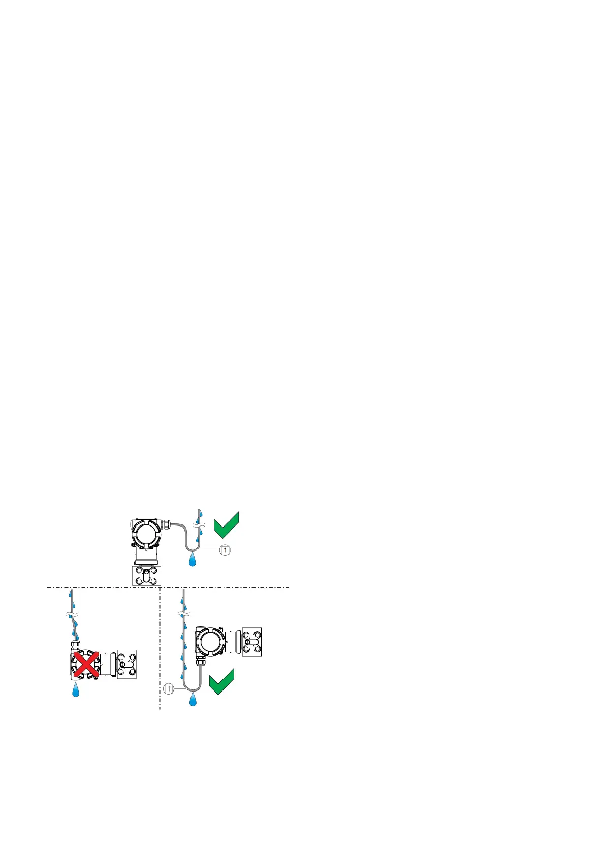
8.6.3 Installing the connecting cables
Ensure that a drip loop (water trap) is used when installing
the connecting cables for the sensor.
If necessary, rotate the transmitter housing accordingly..
NOTICE
If cable glands are not used, the red transport screw
plugs must be replaced with suitable screw plugs when
the transmitter is installed. This is because the transport
screw plugs are not certified as protected against
explosion. This requirement is particularly relevant in
hazardous areas
Cable entries with an M20 x 1.5 thread
Devices with an M20 x 1.5 thread are optional supplied
with factory-installed cable glands and sealing plugs.
Cable entries with a 1/2” NPT thread
The supplied transport sealing plugs do not have IP
rating 4X / IP67 and are not approved for use in
potentially explosive atmospheres.
The transport sealing plugs must be replaced with
suitable cable glands or sealing plugs during device
installation. When selecting the cable glands or sealing
plugs, make sure they have the required IP rating and
explosion protection!
To offer IP rating 4X / IP67, the cable glands / sealing
plugs must be screwed in using a suitable sealing
compound.
Cable entry for PT100 temperature sensor
A metal cable gland should always be used for the Pt100
cable since a shielded cable is used.
Connect the shielding within the metal cable gland!
To offer IP rating 4X / IP67, the cable glands / sealing
plugs must be screwed in using a suitable sealing
compound.
Safety instructions for use in Division 1
Conduit requirements for Div. 1 installations are not
addressed in this procedure. To avoid creating a
hazardous situation, ensure compliance with the
applicable standards, regulations, and recommendations
for installation in the country of use. Resistance
thermometer installation in classified Div. 1
Fig. 9: Installing the connecting cables
1. Drip loop
6.4 Supply requirement
For signal/power connection use twisted, stranded pairs
of wiring no 18 to 22 AWG / 0.8 to 0.35mm2 ø up to 5,000
feet (1500 meters). Longer loops require larger wire.
If a shielded wire is used, the shield should be grounded
only at one end, not both ends. In case of wiring at
transmitter end, use the terminal located inside the
housing marked with the appropriate sign.
For Ex ia and other intrinsically safe approval power supply
must not exceed 30 V DC.
Minimum operating voltage increase to 12.3 V DC with
optional surge protector or to 10.8 V DC with optional
conformity to NAMUR NE 21 (2004).
For maximum power supply voltage please refer to the top
identification plate of the transmitter.
The actual possible line length of the electrical circuit
depends on the total capacitance and resistance, and can
be estimated using the following formula:
6.3 Cable entries
The electrical connection is made via cable entries with a
1/2” NPT or M20 x 1.5 thread.