14 266HSH MODBUS TRANSMITTER | PRESSURE/TEMPERATURE MULTIVARIABLE | OI/266HSHMT-EN REV. A
Follow the instructions in chapter ‘Opening and closing the
transmitter housing’ on page 17 to open and close the
housing safely.
— Observe the power supply limit values in accordance
with the information on the name plate.
— Observe the voltage drop for large cable lengths and small
conductor cross-sections. The voltage at the terminals of the
device may not fall below the minimum value required in
accordance with the information on the name plate.
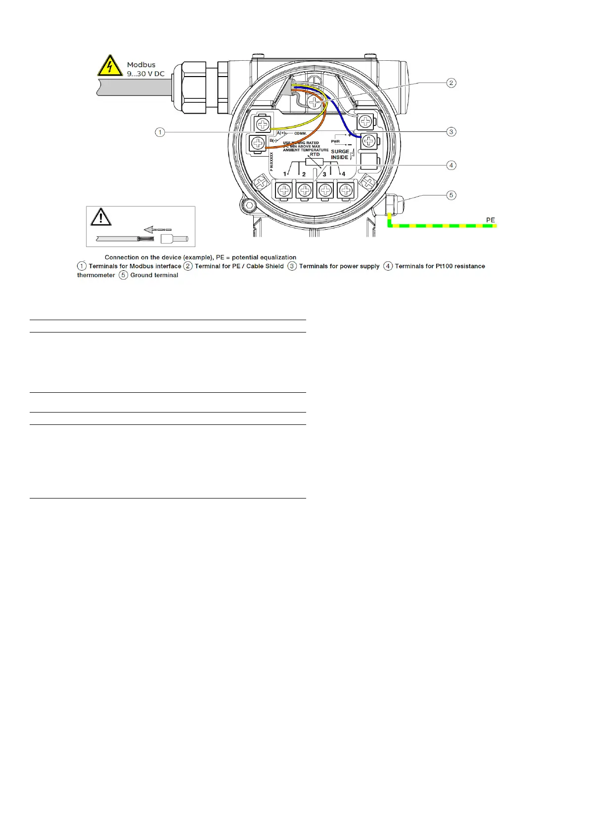
The power supply is connected to terminal PWR + and PWR -,
as stated on the name plate.
To connect the pressure transmitter, observe the
following instructions:
— Lead the cable for the power supply and the
Modbus connection into the terminal box.
— Lead the temperature sensor cable (if there is
one) through the second cable entry and connect it
to the designated terminals.
— Connect the cables in accordance with the
electrical connection diagram. Connect the cable
shields to the designated ground terminal in the
terminal box.
— Connect the potential equalization (PE) on the
ground terminal to the terminal box.
— Use wire end ferrules when connecting.
i
i
Figure 13: