Chapter 2 - Start-Up Instructions
DCS 500B / DCP 500B Operating Instructions IV A 2 - 3
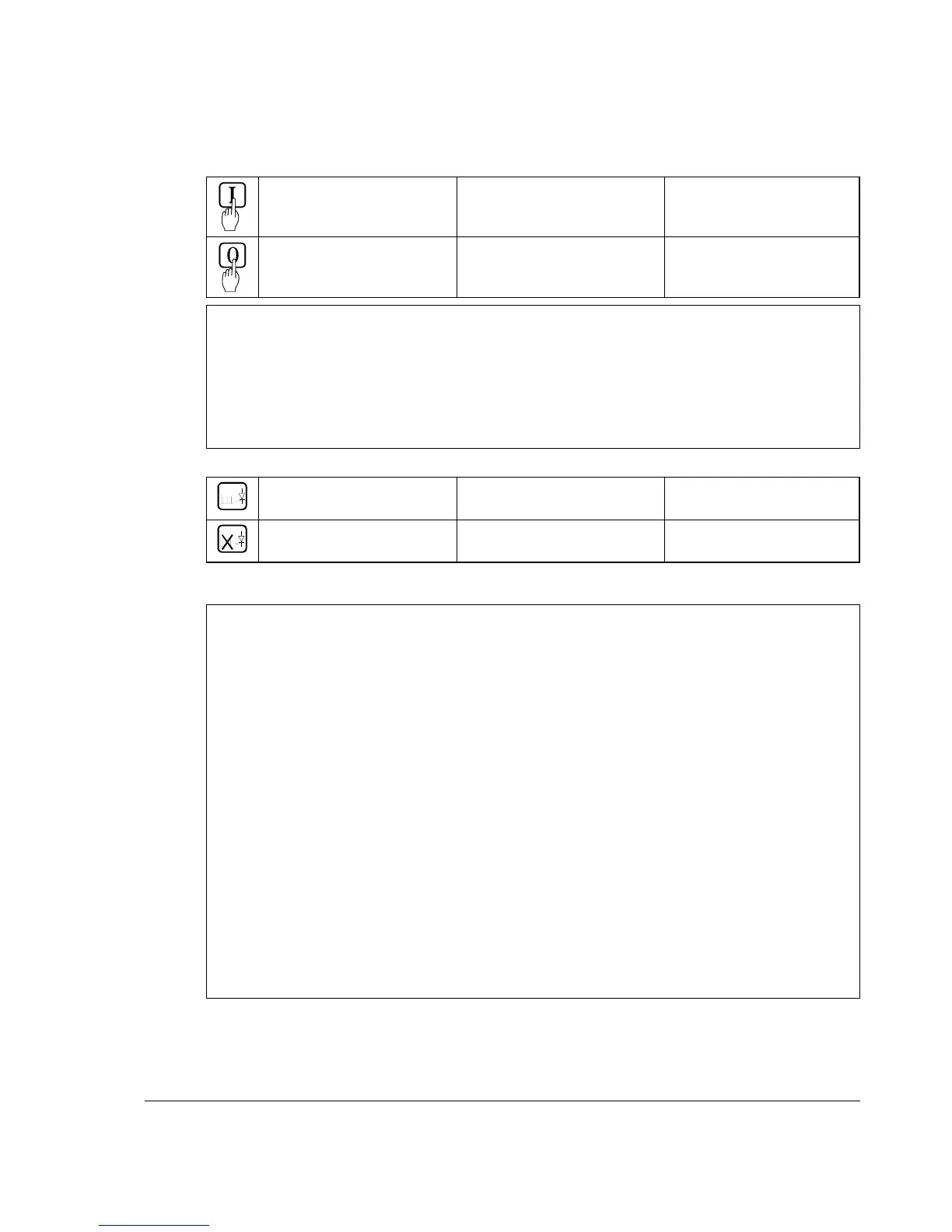
Symbols for switching the electronics or the power section ON and OFF
- Switch ON electronics
- Switch ON power
X6: 7 ⇒ „1“ signal
(K20 in connection example)
(input ON / OFF)
- Switch OFF electronics
- Switch OFF power
X6: 7 ⇒ „0“ signal
(K20 in connection example)
(input ON / OFF)
•
Binary input DI8; designation RUN
For starting the drive, DI8 must be set to logical „1“. This enables the reference at the
REF_SEL and RAMP GENERATOR blocks, as well as the controllers. If DI8 is set to
"0“, the drive will react in accordance with the function set at Parameter 916 (shut-
down with ramp, with torque limit/current limit, with controller block and coasting).
Once ramp-down has been completed (speed feedback below n
min
), the reference is
kept at zero, and the controllers blocked after a time-delay; the drive is torqueless.
Symbols for enabling / disabling the reference
- ENABLE reference
X6: 8 ⇒ „1“ signal
(K21 in connection example)
(input RUN)
- DISABLE reference
X6: 8 ⇒ „0“ signal
(K21 in connection example)
(input RUN)
System-dependent planning
If you want the drive to react with a function other than that of Parameter 916 or 917, you
have to parameterize the unit accordingly, by connecting one of the inputs or an addi-
tional one with a control pin, e.g. at the ramp-function generator.
- Example 1:
Operational ramp-up and ramp-down in the event of reference changes with the same
ramp times, shutdown via RUN with a different time.
Solution:
use second parameter set ramp times; set time at DECEL2;
establish connection from P 1707 to P 10716.
- Example 2:
Implementing an EMERGENCY SHUTDOWN or EMERGENCY STOP function.
Solution:
this function stipulated in various regulations must always be planned in dependence on
the system involved! A basic distinction must be made here between electrical and me-
chanical risks. Since one signal at one input is not sufficient (see above), at least one
other switch-off option must be created, e.g. by means of a relay directly switch-
ing input DI5 to "0“. This is how the power converter attempts (in accordance with
P 917), to defuse the dangerous situation. A dropout-delay contact of the relay will
then switch the power off. If the delay is small or does not match the function selected
for P 917, then certain operating states (regeneration) may, due to laws of physics,
result in the unit fuses tripping, and in extreme cases in thyristor defects.