Operation Manual / 4 Product description / A100-L
8 Disassembly and assembly / 8.11 Fitting the gas inlet casing, nozzle
ring (A180-L and larger)
© Copyright 2018 ABB. All rights reserved. HZTL4034_EN Revision N November 2018
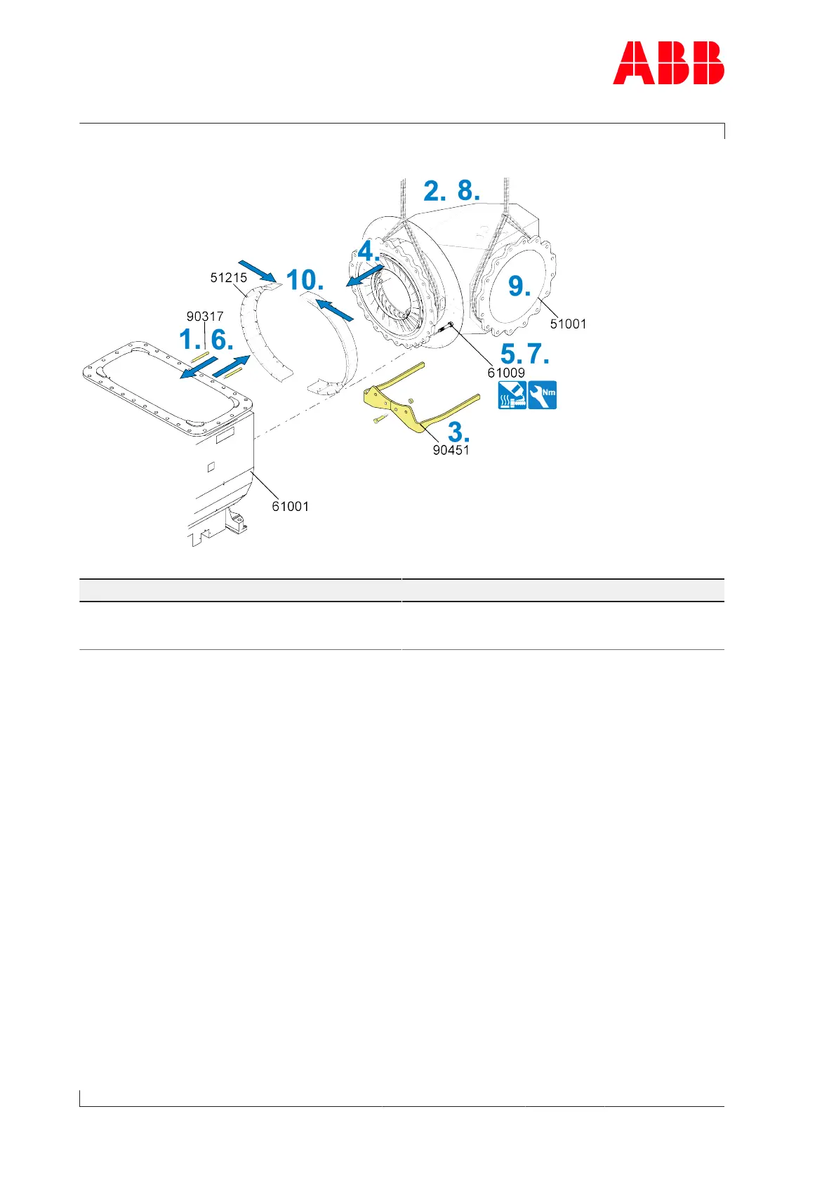
Fitting the gas inlet casing (A180-L and larger) - screwed variant
Fig.53: Fitting the gas inlet casing (A180-L and larger) - screwed variant
Part number A180-L A185-L A190-L
61009 M24
80
1)
Nm
480Nm
M27
100
1)
Nm
700Nm
M30
100
1)
Nm
920Nm
Table37: Tightening torque (61009)
1) Pre-tightening torque of the screws
1. Fit two guide studs(90317) in the upper area on the gas outlet casing(61001).
2. Loop around the gas inlet casing (51001) with the lifting gear and secure it to the crane.
3. Dismantle and remove support (90451) from the gas inlet casing (51001).
4. Push gas inlet casing over the guide studs up to the gas outlet casing (61001).
5. Coat two opposite screws (61009) with high-temperature grease and screw in.
6. Remove the guide studs (90317).
7. Coat remaining screws (61009) with high-temperature grease and fit. Fit the screws by
tightening them crosswise, first to the pre-tightening torque, then to the tightening
torque.
8. Remove the lifting gear.
9. Connect the flanges of the gas inlet casing and the bellows.
10. Fit the insulation segments (51215).
Page 80 / 110