E-Bypass Configurations for ACH550 Drives 35
Start-up
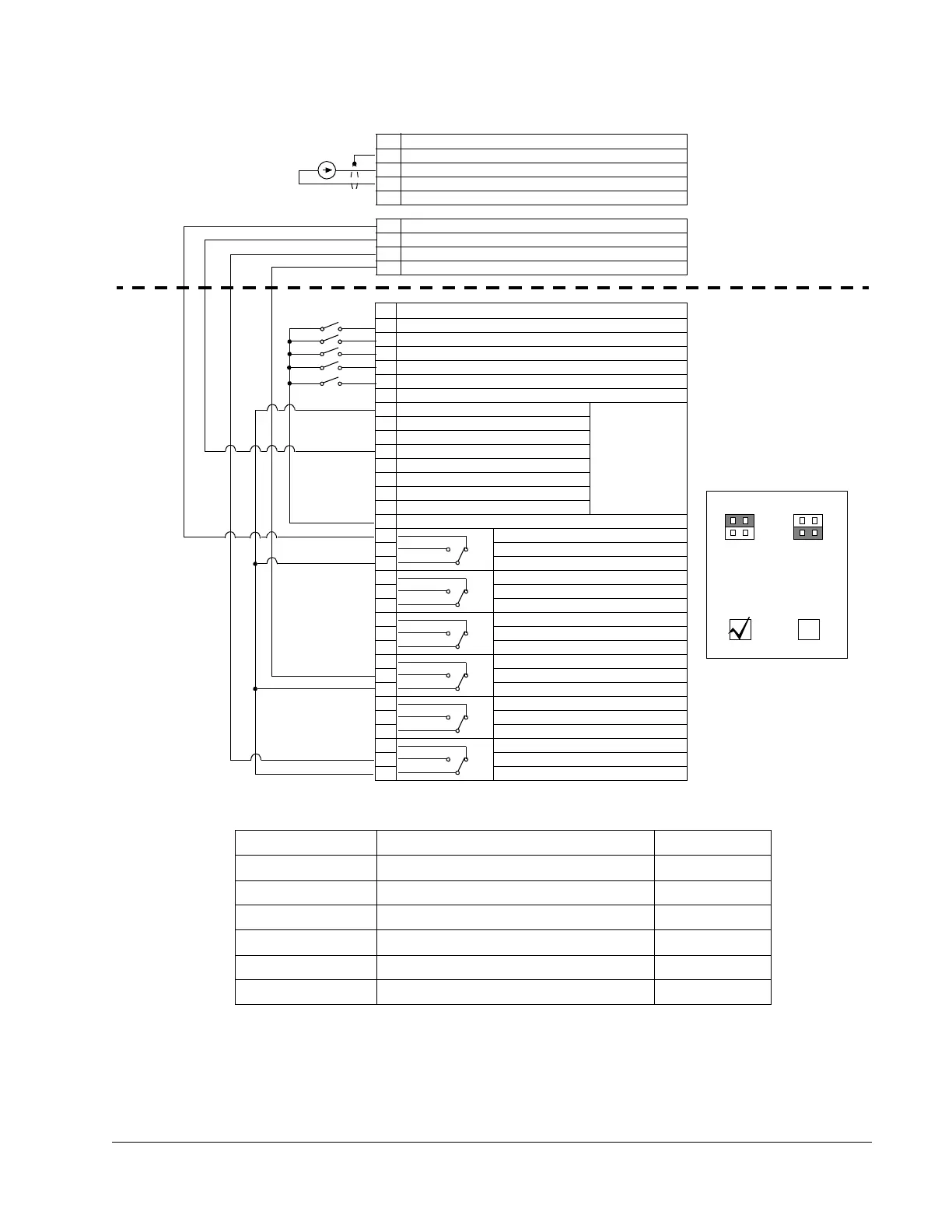
Basic Control Connections for Routing Output Through the ACH550
Parameter Number Description Setting
1001 EXTERNAL 1 COMMANDS 1 (DI1)
1002 EXTERNAL 2 COMMANDS 1 (DI1)
1201 CONST SPEED SEL 0 (NOT SEL)
1601 RUN ENABLE 2 (DI2)
1401 RELAY OUTPUT 1 7 (STARTED)
1403 RELAY OUTPUT 3 3 (FAULT (-1))
ACH550 Drive
E-Bypass
Internally
Supplied
24 VDC
X1 Terminals on ACH550 Control Board
1 Terminal for signal cable shield
2 Analog Input Channel 1
3 Analog Input Common
4 10 V / 10 mA Reference voltage for potentiometer
15 Digital Input 3
16 Digital Input 4
17 Digital Input 5
18 Digital Input 6
X2 Terminals on E-Bypass Control Board
1 Start/Stop
2 Run Enable
3 Safety Interlocks
4 Override 1 – Fireman’s Override
5 Override 2 – Bypass Override
6 I/O Power Supply – Not used
7 ACH550 24V voltage supply Pre-wired to
ACH550
terminal block
X1.
Do NOT
disturb.
8 Start/Stop 2
9 Run Enable 2
10 Safety Output
11 Drive RO3 – N.O.
12 Drive RO3 – Com
13 Drive RO1 – N.C.
14 Drive RO1 – Com
15 Common – Use only with Internal 24 VDC Supply.
16 RO1 – Bypass Fault – N. C.
17 RO1 – Bypass Fault – N. O.
18 RO1 – Bypass Fault – Com
19 RO2 – System Run – N. C.
20 RO2 – System Run – N. O.
21 RO2 – System Run – Com
22 RO3 – System Started – N. C.
23 RO3 – System Started – N. O.
24 RO3 – System Started – Com
25 RO4 – Mode/Override – N. C.
26 RO4 – Mode/Override – N. O.
27 RO4 – Mode/Override – Com
28 RO5 – Drive Fault – N. C.
29 RO5 – Drive Fault – N. O.
30 RO5 – Drive Fault – Com
31 RO6 – Hand/Off/Auto – N. C.
32 RO6 – Hand/Off/Auto – N. O.
33 RO6 – Hand/Off/Auto – Com
Jumper J3
Internal
24 VDC
Powered
I/O
External
115 VAC
Powered
I/O
1
2
1
2