E-Bypass Configurations for ACH550 Drives 45
Technical Data
E- Bypass Control Panel Connections
(Supplement to ACH550-UH User’s Manual)
Control cable requirements for connections to the E-Bypass control panel (X2) are
the same as those described for the ACH550 control panel (X1). Refer to the
ACH550 User’s Manual.
Control Panel Connection Specifications
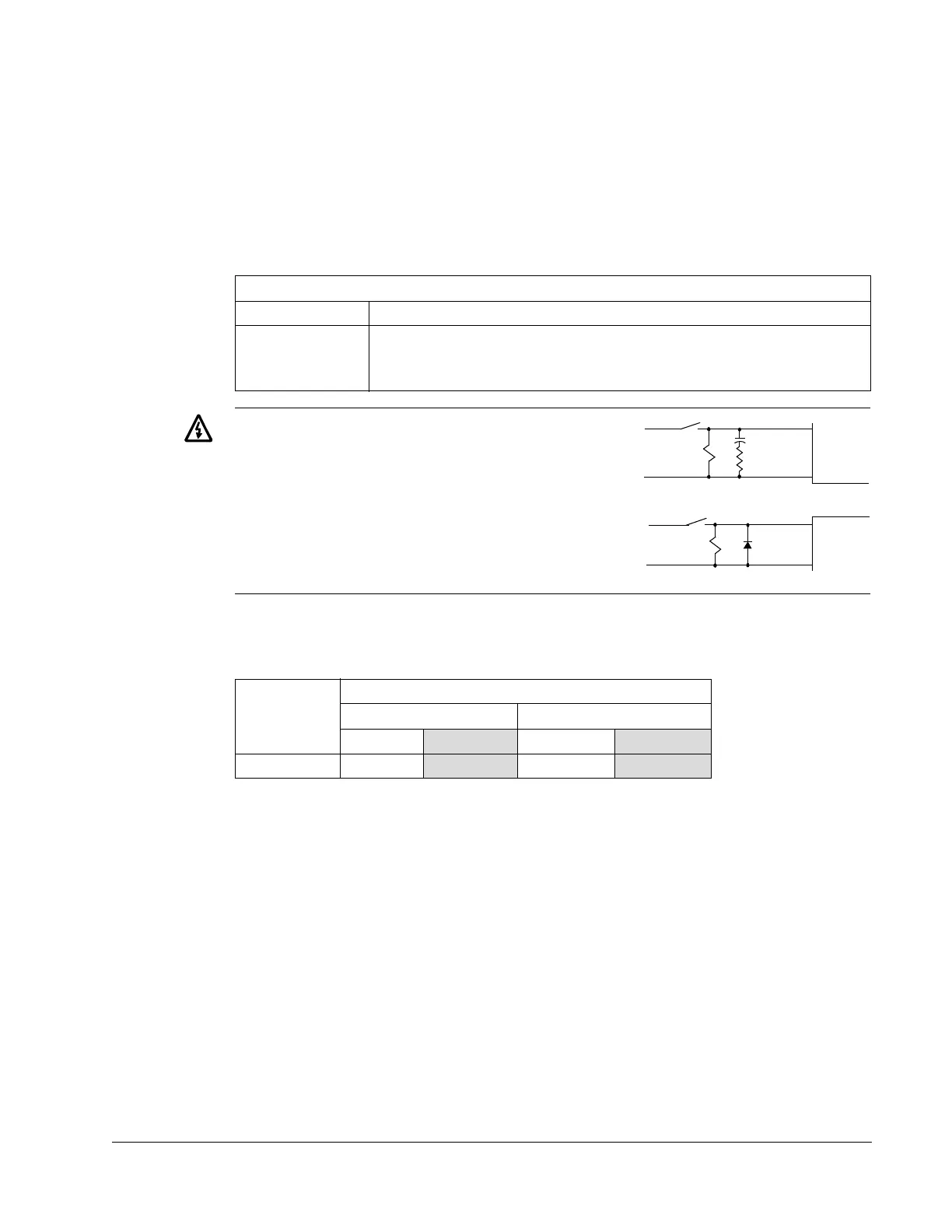
WARNING! Relay coils generate noise
spikes in response to steps in applied
power. To avoid drive damage from such
spikes, all AC relay coils mounted across
control panel inputs require R-C snubbers,
and all DC relay coils mounted across
control panel outputs require diodes – see
figure.
Control Panel Terminals
The following table provides specifications for the E-Bypass’s control terminals
Control Connection Specifications
Digital Inputs Digital input impedance 1.5 kΩ. Maximum voltage for digital inputs is 30 V.
Relays
(Digital Outputs)
• Max. contact voltage: 30 V DC, 125 V AC
• Max. switching current: 8 A, 24 V DC; 0.4 A at 125 V AC
• Max. continuous current: 2 A rms
Frame Size
Control
Maximum Wire Size Torque
mm
2
AWG Nm lb-ft
All 0.12…2.5
26…14 0.4 0.3
33 Ohm
0.47 uF
AC Coil
Contro
Typical R-C
Snubber
DC Coil
Diode
+
-
Panel
Inputs
Contro
Panel
Output