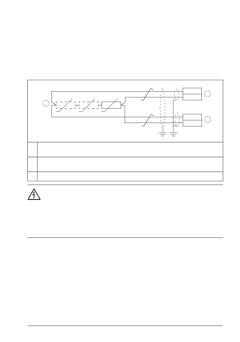
■ AI1 and AI2 as Pt100, Pt1000, Ni1000, KTY83 and KTY84 sensor inputs
(X1)
Sensors for motor temperature measurement can be connected between an analog
input and output, an example connection is shown below. Leave the other end of the
shield unconnected or ground it indirectly via a few nanofarads high-frequency capacitor,
for example, 3.3 nF / 630 V. The shield can also be grounded directly at both ends if
they are in the same ground line with no significant voltage drop between the end points.
One, two or three Pt100 sensors; one, two or three Pt1000 sensors; or one Ni1000, KTY83
or KTY84 sensor
1
Set the input type to voltage for analog input AI1 or analog input AI2 with parameters. Set
the appropriate analog input unit to V (volt) in parameter group 12 Standard AI.
2
Select the excitation mode in parameter group 13 Standard AO.
3
WARNING!
As the inputs pictured above are not insulated according to IEC 60664, the
connection of the motor temperature sensor requires double or reinforced insulation
between motor live parts and the sensor.
If the assembly does not fulfill this requirement, the I/O board terminals must be
protected against contact and must not be connected to other equipment or the
temperature sensor must be isolated from the I/O terminals.
■ Safe torque off (X4)
For the drive to start, both connections (+24 V DC to IN1 and +24 V DC to IN2) must
be closed. By default, the terminal block has jumpers to close the circuit.
Remove the jumpers before connecting an external Safe torque off circuitry to the drive.
See also chapter The Safe torque off function (page 273).
Note: Only 24 V DC can be used for STO. Only PNP input configuration can be used.
Control unit 147


 To Next Page