6
Heat Dissipation Requirements
Ensure that the mounting surface is capable of conducting power losses
from the power circuit into the environment. The maximum temperature of
the mounting plate may not exceed 80 °C under any circumstances.
The table below gives the power losses and minimum surface area
requirements, when a 3 mm plate, capable of dissipating heat from both
sides, is used as a heatsink (max. ambient temperature 40 °C). The 3 mm
steel plate is only one example, any kind of external heatsink can be used if
it meets the mounting surface and heat dissipation requirements.
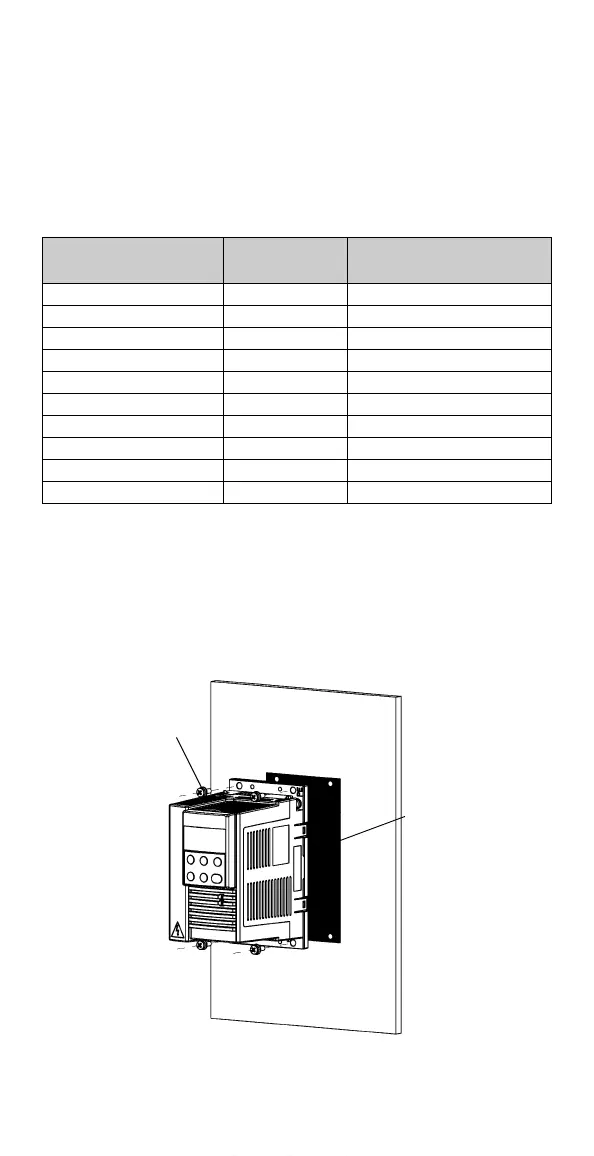
Mechanical Installation
• Clean the mounting surface.
• Apply thermal grease between the ACS140 and the mounting surface.
• Use M4 screws, mounting torque 1-1.5 Nm.
After installation, verify the thermal design by monitoring the temperature
(parameter 0110) of the ACS140. The thermal design is successful if the
ACS140 temperature does not exceed 85 °C under full load and maximum
ambient temperature.
Converter Type Power Loss (W)
Minimum Area H x W
(mm x mm)
ACS141-H18-1 7 150 x 150
ACS141-H25-1 10 180 x 180
ACS141-H37-1 12 200 x 200
ACS141-H75-1 13 210 x 210
ACS141-1H1-1 19 250 x 250
ACS141-1H6-1 27 300 x 300
ACS143-H75-3 14 220 x 220
ACS143-1H1-3 20 260 x 260
ACS143-1H6-3 27 300 x 300
ACS143-2H1-3 39 500 x 500
Four M4
screws
Thermal
grease
www.barghmaher.org