7
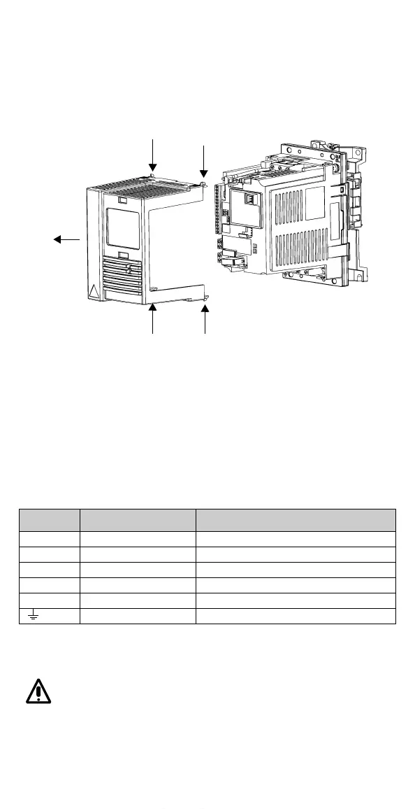
D Removing the Cover
1 Press the four snap-on buttons on the top and bottom corners of the unit
simultaneously.
2 Remove the cover.
E Attaching a Warning Sticker
The packing box includes warning stickers in different languages. Attach a
warning sticker in the language of your choice to the place on the inside
plastic skeleton as indicated above, in section G, “Terminal Interface”.
F Cable Connections
Follow local rules for cable cross-sections. Use shielded motor cable.
Route the motor cable away from control wires and the power supply cable
to avoid electromagnetic interference.
Note! See "ACS140 EMC Instructions" on page 85.
Terminal Description Note
L, N 1~ power supply input In figure below (see G), a 3~ unit is shown.
U1, V1, W1 3~ power supply input Do not use in 1~ supply!
PE Protective Earth Min. 4 mm
2
Cu wire.
U2, V2, W2 Power output to motor Max. cable length depends on the unit type, (see R)
Uc+,Uc- DC bus For optional ACS braking unit/chopper.
Motor cable shield
1
1
2
www.barghmaher.org