50
1103 EXT REF1 SELECT
This parameter selects the signal source of external reference 1.
0 =
KEYPAD
Reference is given from the control panel.
1 = AI 1
Reference is given through analogue input 1.
2 = AI 2
Reference is given through analogue input 2.
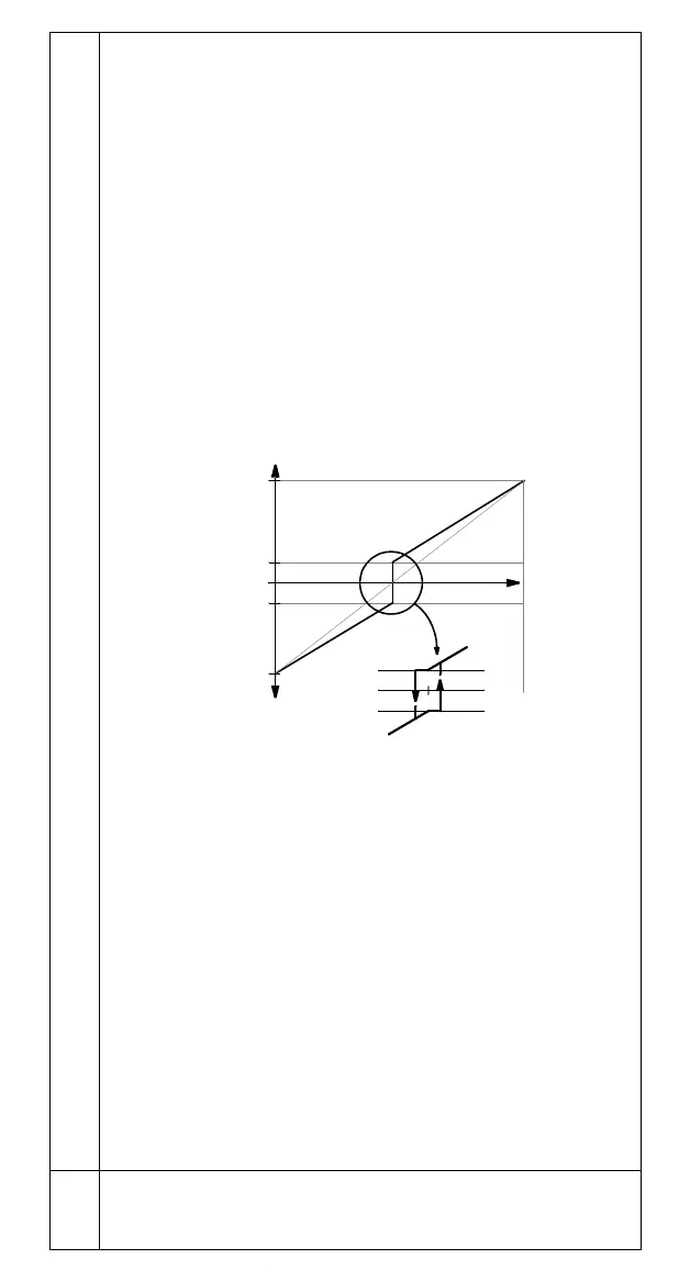
3 = AI1/
JOYST; 4 = AI2/JOYST
Reference is given through analogue input 1 (or 2 accordingly) configured for a
joystick. The minimum input signal runs the drive at maximum reference in the
reverse direction. The maximum input signal runs the drive at maximum
reference in the forward direction (See Figure 2). See also parameter 1003
DIRECTION.
Caution: Minimum reference for joystick should be 0.3 V (0.6 mA) or higher. If a
0 ... 10 V signal is used, the ACS140 will operate at maximum reference in the
reverse direction if the control signal is lost. Set parameter 3013
AI1 FAULT LIMIT
or 3014
AI2 FAULT LIMIT to a value 3 % or higher, and parameter 3001 AI<MIN
FUNCTION to 1 (FAULT), and the ACS140 will stop in case the control signal is
lost.
Figure 2 Joystick control. Maximum for external reference 1 is set with
Parameter 1105 and minimum with Parameter 1104.
5 = DI3U,4D(R)
Speed reference is given through digital inputs as motor potentiometer control.
Digital input DI3 increases the speed (the U stands for “up”), and digital input
DI4 decreases the speed (the D stands for “down”). (R) indicates that the
reference will be reset to zero when a Stop command is given. The rate of
change of the reference signal is controlled by parameter 2204
ACCELER TIME 2.
6 = DI3U,4D
Same as above, except that the speed reference is not reset to zero on a Stop
command. When the ACS140 is started, the motor will ramp up at the selected
acceleration rate to the stored reference.
7 = DI4U,5D
Same as above, except that the digital inputs in use are DI4 and DI5.
8=
COMM
The reference is given through serial communication.
9 = DI3U,4D(R,NC); 10 = DI3U,4D(NC); 11 = DI4U,5D(NC)
Selections 9,10,11 are the same as selections 5,6,7 respectively, with the
exception that the reference value is not copied when:
• moving from EXT1 to EXT 2, or
• moving from EXT2 to EXT1, or
• moving from local to remote.
1104 EXT REF1 MIN
Sets the minimum frequency reference for external reference 1 in Hz. When
analogue input signal is at minimum, external reference 1 equals to
EXT REF1
MIN. See Figure 3.
EXT REF1 MAX
+2%
-2%
EXT REF1 MIN
- EXT REF1 MIN
- EXT REF1 MAX
2V / 4mA
0V / 0mA
EXT REF
- EXT REF
10V / 20mA
Hysteresis 4% of
Full Scale
1 MIN
1 MIN
www.barghmaher.org