Additional data for calculating the rise time and the peak line-to-line voltage
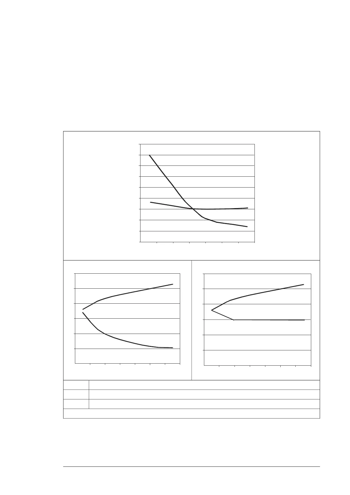
The diagrams below show the relative peak line-to-line voltage and rate of change of voltage
as a function of the motor cable length. If you need to calculate the actual peak voltage and
voltage rise time considering the actual cable length, proceed as follows:
•
Peak line-to line voltage: Read the relative Û
LL
/U
N
value from the diagram below and
multiply it by the nominal supply voltage (U
N
).
•
Voltage rise time: Read the relative values Û
LL
/U
N
and (du/dt)/U
N
from the diagram
below. Multiply the values by the nominal supply voltage (U
N
) and substitute into equation
t = 0.8 · Û
LL
/(du/dt).
Inverter without du/dt filter
Û
LL
/U
N
l (m)
du/dt
U
N
-------------(1/μs)
1.0
2.0
5.0
4.0
3.0
1.5
2.5
3.5
4.5
100 200 300
5.5
Inverter frame size R8i with du/dt filter
.5
3.0
l (m)
du/dt
U
N
-------------(1/Ps)
Û
LL
/U
N
Inverter frame sizes R1i … R7i with du/dt filter
100 200 300
0.0
0.5
1.0
1.5
2.0
2.5
3.0
l (m)
du/dt
U
N
-------------(1/μ s)
Û
LL
/U
N
Motor cable length
I
Relative peak line-to-line voltage (du/dt filter in use)
Û
LL
/U
N
Relative du/dt value (du/dt filter in use)(du/dt)/U
N
Note: Û
LL
and du/dt values are approximately 20% higher during the resistor braking.
Additional note for sine filters
A sine filter also protects the motor insulation system. The peak phase-to-phase voltage
with a sine filter is approximately 1.5 · U
N
. Check the availability of the sine filter from ABB.
Electrical planning guidelines 23

 Loading...


